Machine Designing. Part 2
Description
This section is from "Scientific American Supplement". Also available from Amazon: Scientific American Reference Book.
Machine Designing. Part 2
Many of the modern builders of what Chordal calls the hyphen Corliss engine claim to have made a great advance by putting a post under the center of the frame, but whether in acknowledgment that the frame would be likely to go down or the stonework come up I could never make out. What I should fear would be that the stone would come up and take the frame with it. Every brick mason knows better than to bed mortar under the center of a window sill; and this putting a prop under the center of an engine girder seems a parallel case. They say Mr. Corliss would have done the same thing if he had thought of it. I do not believe it. If Mr. Corliss had found his frames too weak, he would soon have found a way to make them stronger.
John Richards, once a resident of this city, and likely the best designer of wood-working machinery this country, if not the world, ever saw, pointed out in some of his letters the true form for constructing machine framing, and in a way that it had never been forced on my mind before. As dozens, yes, hundreds, of new designs have been brought out by machine tool makers and engine builders since John Richards made a convert of me, without any one else, so far as I know, having applied the principle in its broadest sense, I hope to present the case to you in a material form, in the hope that it may be more thoroughly appreciated.
The usual form of lathe and planer beds or frames is two side plates and a lot of cross girts; their duty is to guide the carriages or tables in straight lines and carry loads resisting bending and torsional strains. If a designer desires to make his lathe frame stronger than the other fellows, he thinks, if he thinks at all, that he will put in more iron, rather than, as he ought to think, How shall I distribute the iron so it will do the most good?
In illustration of this peculiar way of doing things, which is not wholly confined to machine designers, I should like to relate a story, and as I had to carry the large end of the joke, it may do for me to tell it.
While occupying a prominent position, and yet compelled to carry my dinner, my wife thought the common dinner pail, with which you are probably familiar (by sight, of course), was not quite the thing for a professor (even by brevet) to be seen carrying through the streets. So she interviewed the tinsmith to see if he could not get up something a little more tony than the regulation fifty-cent sort. Oh, yes; he could do that very nicely. How much would the best one he could make cost? Well, if she could stand the racket, he could make one worth a dollar. She thought she could, and the pail was ordered, made, and delivered with pride. Perhaps you can guess the result. A facsimile of the original, only twice the size.
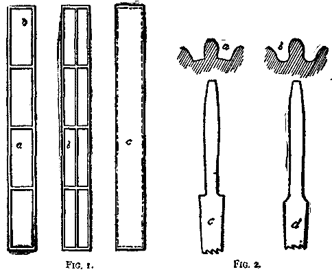
Now, this is a very fair illustration of the fallacy of making things stronger by simply adding iron. To illustrate what I think a much better way, I have had made these crude models (see Fig. 1), for the full force of which, as I said before, I am indebted to John Richards; and I would here add that the mechanic who has never learned anything from John Richards is either a very good or very poor one, or has never read what John Richards has written or heard what he has had to say.
Three models, as shown in Fig. 1, were exhibited; all were of the same general dimensions and containing the same amount of material. The one made on the box principle, c, proved to be fifty per cent. stiffer in a vertical direction than either a or b, from twenty to fifty times stiffer sidewise, and thirteen times more rigid against torsion than either of the others.
However strong a frame may be, its own weight and the weight of the work upon it tends to spring it unless evenly distributed, and to twist it unless evenly proportioned. For all small machines the single post obviates all trouble, but for machine tools of from twice to a half dozen times their own length the single post is not available. Four legs are used for machines up to ten feet or so, and above that legs various and then solid masonry. If the four legs were always set upon solid masonry, and leveled perfectly when set, no question could be raised against the usual arrangement, unless it be this: Ought they not to be set nearly one-fourth the way from the end of the bed? or to put it in another form: Will not the bed of an iron planing machine twelve feet in length be equally as well supported by four legs if each pair is set three feet from the ends - that is, six feet apart - as by six legs, two pairs at the ends and one in the center, and the pairs six feet apart? there being six feet of unsupported bed in either case, with this advantage in favor of the four over the six, settling of the foundation would not bend the bed.
It is not likely that one-half of the four-legged machine tools used in this country are resting upon stable foundations, nor that they ever will be; and while this is a fact, it must also remain a fact that they should be built so as to do their best on an unstable one. Any one of the thousand iron planing machines of the country, if put in good condition and set upon the ordinary wood floors, may be made to plane work winding in either direction by shifting a moving load of a few hundred pounds on the floor from one corner of the machine to the other, and the ways of the ordinary turning lathe may be more easily distorted still. Machine tool builders do not believe this, simply because they have not tried it. That is, I suppose this must be so, for the proof is so positive, and the remedy so simple, that it does not seem possible they can know the fact and overlook it. The remedy in the case of the planer is to rest the structure on the two housings at the rear end and on a pair of legs about one-fourth of the way back from the front, pivoted to the bed on a single bolt as near the top as possible.
Continue to:
My Books

