


Automatic Greenhouses. A Revolution In Glass Houses - An Invaluable Invention Given Away To Our Readers
Description
This section is from the book "The American Garden Vol. XI", by L. H. Bailey. Also available from Amazon: American Horticultural Society A to Z Encyclopedia of Garden Plants.
Automatic Greenhouses. A Revolution In Glass Houses - An Invaluable Invention Given Away To Our Readers
IN THE April number of The American Gardner there appeared a description of a new greenhouse erected by Charles Barnard, at Stamford, Conn. Since that time further research has been carried on in the same line of work, and The American Garden has now secured the right to publish a detailed account of the experiments made by Mr. Barnard. No patents will be taken out on the inventions and improvements in heating and ventilating greenhouses, and any one is at liberty to make and use the buildings and apparatus here described. It is the aim to present the plan to the horticultural public in the hope that it will be of value to all who use glass in gardening. There is just now a rapidly-growing interest in the whole subject of culture under glass, and it is hoped that The American Garden, in laying Mr. Barnard's ideas before the public, will encourage many to use glass, both for business and pleasure.
The first feature of the new house is its portability. The building was made in six parts, two back or rear wall portions, two front wall portions and two end pieces, one containing the door. As the soil was a heavy clay, and wet, a cellar 18 inches deep was prepared, and a single wall of stone laid for a foundation. The wall was also supplemented with rough boarding and banks of earth on the outside. . In erecting such a house it is very important to secure a good foundation - air, frost and water-tight. The aim is to build an air-tight greenhouse, and for this purpose special attention should be given to the foundation, hard bricks laid in cement being probably the best. In dry soil the cellar may be three feet deep, as the deeper the structure in the ground the warmer it will be. A deep cellar also economizes in building the walls. Next to dryness and depth is shelter, and a building, hill-side, or even trees, to keep off the west and north winds will save money in the fuel bill.
The walls of the house were formed of a frame of 2x3 scantling, each section being simply framed at each end and top and bottom. On the outer face was nailed matched 7/8J-inch boards, planed on one side.
Next to this was tacked on the inside a lining of cow-bair felt one inch thick. Inside, the frame was again covered with matched boards, leaving an air space of one inch between the felt and the inside boarding. The lower piece of the frame formed the sill, and the upper piece was cut diagonally to form the support for the sash. The diagram (Fig. 1) shows a cross-section of the frame,lining and boarding. It will be seen that the outside boarding is longer than the inside. This was for the purpose of forming a wind-break or guard against the north wind. The west-end section was also formed in the same way and for the same purpose.
Each section had a joint or rabbet, and when the sections were put up in place, long screws were put through the rabbeted joints, thus holding the structure together. The sash were common hot-bed sash, and when the walls were in place they were laid on top, the end sashes covering the end walls. Strips of cloth were placed under each sash where-ever they rested on the walls, and the sash were screwed down on the cloth to make an air-tight joint. The joints between the sash were covered with battens. Figure 2 shows the structure of the front and rear walls with the boarding, felting, air space and sash. The door, placed in the east end of the house, was made like the walls, with felt lining, and was hung with a tight-fitting joint. The building was practically a refrigerator, and was designed to be, like the large refrigerators in meat stores, as nearly air-tight as possible, and, unlike a refrigerator, to keep cold out instead of keeping heat out.

Section of Rear Wall.
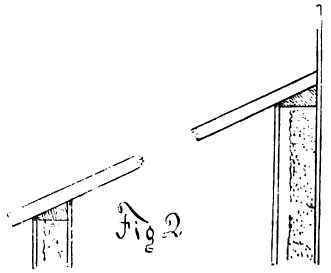
Section of Walls and Showing Position of Sash.
The building measured x8 feet (6 sash) over all on top. The rear wall was 6½ feet high on the outside and 5½ feet inside. The front wall was 3 feet 3 inches high on the outside. The sash were 6 feet long, which gave, with the proper slope, a clear space inside of 5 feet 8 inches. The interior length was about 17 feet. The cellar being 18 inches deep gave ample head room at the rear. The table extended across the west end and was 15 feet long, giving a table surface of 51 square feet, and shelving at the back and ends gave a total of 74 square feet of available space for plants. Rhubarb was also cultivated under the table.
It will be observed that no means are provided for raising the sash to secure ventilation. To per-mit the warm air to escape and to exclude cold drafts, four lights of glass were taken out at the upper end of one sash near the middle of the house. This gave four openings, 8x10 inches, 320 square inches. On these openings was placed a wooden box or trunk, 12 inches high at the back and with a flat roof or hood. In the center of this trunk was cut a round opening 12 inches in diameter, and over this was placed a sheet-metal chimney, having a cap or hood at the top, the chimney being 18 inches high. Within the trunk was a valve carefully balanced in the middle and fitting tight when closed. Figure 3 gives a section showing the ventilating trunk, chimney and valve in position on top of the sash. The trunk was three feet long and 15 inches wide.
It will be seen that this system of ventilating keeps out all back drafts or cold winds that, by the usual method of ventilating, are sure to blow down on the plants. Experience with this ventilator in actual operation over several months, including cold, windy days in March with hot sunshine, shows that it was ample to keep the house at any required temperature. The actual outlet for the hot air was only 12 inches in diameter, but it was sufficient, because the valve began to open the instant the heat began to accumulate. Being automatic, there was no delay waiting for some one to open the house, and the instant the temperature rose above a certain point (say 8o°) the valve began to open, and as soon as it was open, even a quarter of an inch, the hot air began to go out. In like manner the moment the temperature began to fall the valve began to close. Even a cloud passing over the sun caused the valve to move, and if the cloud remained more than a few moments, the valve would completely close, thus cutting off the waste heat. The manner of operating the valve was very simple. A large thermostat was hung on the under side of the sash and connected by balanced rods and bell-joints with the valve.
Continue to:


My Books

