(12) Sensory Threshold For Visual Efficiency
Description
This section is from the book "Human Vitality And Efficiency Under Prolonged Restricted Diet", by Francis G.BENEDICT, Walter R. Miles, Paul Roth, And H. Monmouth Smith. Also available from Amazon: Human Vitality and Efficiency Under Prolonged Restricted Diet.
(12) Sensory Threshold For Visual Efficiency
The general arrangement of the apparatus for the measurement of visual "acuity" is indicated by the schematic diagram in figure 39. The subject occupied a position at the left end of the apparatus while the operator was at the right, where he could manipulate the test object and record the readings, but be entirely hidden from the view of the subject. When the subject is in position against the head-rest R the artificial pupil P is in convenient position for the right eye. The line of vision is f romPthrough a diaphragm opening, D, through the hood H, with its several screens S which reduce to a negligible quantity the reflected light from the four sides of the hood, to the test object 0. In a suitable in-closure LH a lamp is arranged so that the light is reflected at X and thrown through the test-object window. The test object is manipulated by the micrometer adjustment M. The head-rest was the same as that used in connection with the eye-reaction test (see fig. 32, p. 162). A in figure 32 represents the artificial pupil and its mounting, shown as P in figure 39. The dark blind B in figure 32 was in front of the subject's left eye. The lens of the camera, which usually is directly in front of the right eye (see fig. 35) was withdrawn and in its place a telescoping tube 5 cm. in diameter and 28 cm. in length was put in position. The end of the tube near the subject carried a small projection which was suitable for adapting the apparatus to the contour of the subject's face. At the end of this projection the artificial pupil was located. The whole telescoping tube (T in fig. 39) could be moved easily, so that the artificial pupil was as close as convenient to the eye of the subject. The distance was usually not more than 1 cm. At the other end of the tube there was a diaphragm (see D in fig. 39). The round opening in this was 12 mm. in diameter. Its use and importance will become clear in later paragraphs.
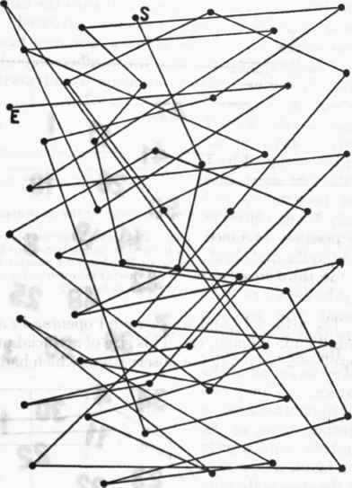
Fig. 38. - The movement pattern which should be followed by the hand in pointing out the numbers in order.
S, start of test; E, end.
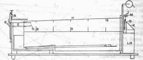
Fig. 39. - Arrangement of apparatus for the measurement of visual efficiency.
LH. lamp house; X, mirror to reflect light through the test object, O; M, micrometer for ad Justine width of test bands in O; H, hood excluding extraneous light; S, velvet screens to reduce reflected light from walls of hood; T, telescoping member at one end of which is the diaphragm, D, for limiting the area of view; at the other end the artificial pupil, P, is placed near the subject's eye; R, head-rest shown in figure 32.
The artificial pupil was a round opening in a flat black surface'and was 3 mm. in diameter. This size of artificial pupil was adopted as the result of a large series of observations which had been carried out previous to the present research. Data for this factor are shown in the curves of figure 40. These curves are based on about 1,200 threshold determinations on one subject, who served on different days, but under conditions which may be considered as uniform. Optimum vision is found to be with an opening of 3 mm., which is much better than an opening of 2 mm., but not significantly better than one of 4 mm. This agrees thoroughly with the findings published by Cobb.1
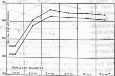
Fig. 40. - Visual efficiency with different diameters of artificial pupil. The ordinate marked 5 mm.* shows results when no artificial pupil was used.
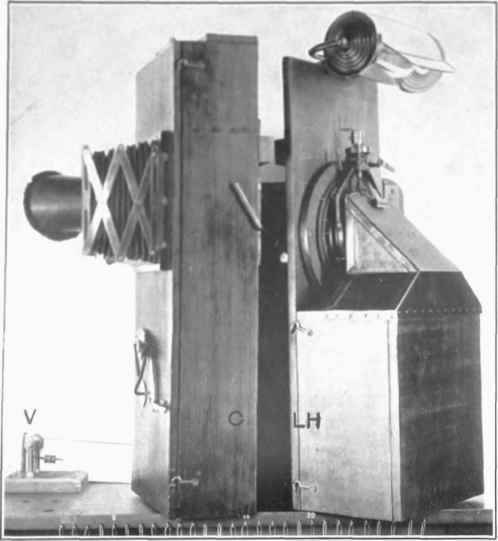
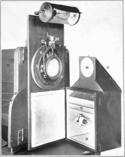
Fig. 41. - General arrangement for shifting the visual acuity object into the position commonly occupied by the falling plate camera. V, device for moving the camera to the left as required for photographing several eye reactions on the same plate; C, falling plate camera; LH, lamp house and visual acuity object.
Fig. 42. - Details of the visual test object, its mounting and means of illumination.
R and R', two rings in which are mounted two glass gratings; L, three lugs to hold R and R' in position for rotation; Y, yoke to rotate R and R' in opposite direct inns against the tension of spring, 8, when operated by the micrometer, M; D, scale of degrees for setting instrument to different axes; C, clamp; B, mirror; G, two plates of ground glass for diffusion of light; X, mirror; W, milk-glass window; H, hood for excluding outside illumination.
The falling-plate camera, which, when in use, is at the right-hand end of the hood (see H in the diagram in fig. 39), is so hinged that it may be swung to the left and the visual-acuity object made to take its position at the end of the hood. This arrangement is evident in figure 41. Here the camera C has been swung partly out, but not far enough to allow LH, the lamp house, carrying the visual-acuity object, to come into position. The opening at the farther end of the hood may be seen as a bright spot between the camera and the lamp house.
The test object here used for determining the visual efficiency was one in which the width of a set of alternately dark and light bands could be continuously varied without changing in any way other factors in the stimulus field. The average brightness of the field is the same for all widths of lines.
Continue to:
My Books

