Sensory Threshold for Electric Shock. Part 3
Description
This section is from the book "Human Vitality And Efficiency Under Prolonged Restricted Diet", by Francis G.BENEDICT, Walter R. Miles, Paul Roth, And H. Monmouth Smith. Also available from Amazon: Human Vitality and Efficiency Under Prolonged Restricted Diet.
Sensory Threshold for Electric Shock. Part 3
To avoid extraneous induction effects and disturbances from other electrical conductors and from the capacity of the earth, the electrical circuit shown in the diagram in figure 43 should be as compact as possible. The total length of wire, other than the drop-wire and the resistance which was employed in the circuit should be as short as is at all compatible with the other conditions desired for the measurements. The pendulum key was used in the same room with the subject, who was about 10 feet distant from it. The noise made by the action of the device is thus a factor to be considered when it is used for threshold determination. The most annoying sound, and one which came just at a moment when the subject should not be disturbed, was from the catching of the pendulum after it had opened the switches. At such a time the pendulum produced a very objectionable thud when the catch was made of metal. Finally a simple and very satisfactory arrangement was found, the detail of which is shown in figure 46. A rather heavy 2-inch rubber band R is lightly stretched between two points, B and C, and held in a slightly twisted position. The rounded end of the arm A, swinging up from the lower right-hand corner as shown in the figure, can easily pass under, but having passed, can not return. A soft leather sleeve S encircles the band and greatly diminishes the weat on the rubber. It also decreases the resistance which must be overcome by the arm A in passing under. The sleeve tends to roll on the rubber band; the position of wear is thus continually shifted. This form of catch is without objectionable sound and, in fact, is almost noiseless.
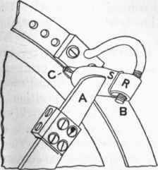
Fig. 46. - Arrangement for noiselessly catching the pendulum at the end of its swing.
R, rubber band, lightly stretched and slightly twisted between points B and C; A, the pendulum arm which, because of its shape and the position of the rubber band, may pass from right to left but can not return; S, leather sleeve to reduce wear and friction on rubber.
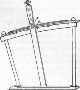
Fig. 47. - Slow-motion control for changing the separation between the switches opened by the pendulum.
R and P, rack and pinion device.
The handle H, shown incomplete in figure 44, extends 75 cm. beyond the periphery of the disk and, passing through a table above the pendulum, is arranged for slow movement with a rack-and-pinion device as shown in figure 47 (see R and P). By this means the separation of the switches S and S' (figure 44) may be continuously and accurately varied if desired. In the reduced-diet investigation the separation of the switches S and S' was always the same, 5°, representing a shock duration of about 0.0035 second, and only the voltage was changed. It is of course evident that the voltage might be held constant and the threshold determined by changing the duration of the shock by shifting the position of S' with the slow-motion control of figure 47. Unpublished experiments have shown that a threshold may be determined in this way.
The electrodes which were used for this measurement recommend themselves for several reasons. In the first place, it is of prime importance in making sensory measurements with the fingers as receptors that the hand should be in a normal and comfortable position. The arm should be supported, the hand relaxed, the fingers should not be required to span from one vessel of solution to another in such a way that the muscles are tense and must be frequently rested. The form of the electrodes employed in the present research and the convenience of their application may be seen in figure 48. A two-compartment glass vessel (pickle-dish), each compartment 8 by 9 cm. in area and 2.5 cm. deep, was suitably supported at a level conveniently below that of the armrest. Soft pads were provided which the subject could arrange under the palm of the hand according to his own desire and comfort. Two fingers could very easily be placed in the salt solution, one on either side of the narrow glass partition. Two porous clay cups, one located in each compartment, contained a saturated solution of zinc sulphate. Amalgamated sine rods were also placed in the porous cups. Thus the electrodes were comfortable and non-polarizable. The liquid could be brought to body temperature and easily controlled by the small electric heater which was located below the electrodes. Another point in favor of these electrodes, involving considerable economy of tune, was that the area of each compartment was sufii-dently large in comparison to the volume of the finger-tips immersed in them to make it unnecessary to adjust the height of the solution for each subject. The depth of immersion employed was 2 cm.
Figure 48, which has just been described, shows the fingers of the subject in position for stimulation. In figure 49 the hands of the operator are shown in position for taking the threshold measurements. This apparatus and the hands of the operator are of course entirely-hidden from the subject who is being tested. The apparatus in figure 49 is as follows: A drop-wire D is composed of 750 turns, with a total resistance of 490 ohms, rated for constant use at 0.7 amperes. Fine adjustments in voltage may be made by the large handle which is seen grasped by the left hand. V is a voltmeter of standard make and R a non-inductive resistance, 1 megohm in 10 steps; 200,000 ohms were employed. The control switch C is a modified form of Durig switch, the modification consisting chiefly in the shape of the glass vacuum bulbs B and B', through the ends of which platinum wires extend. The contact is completed inside each bulb by 1 c. c. of mercury. In this switch the bulbs have been curved so that when it is in a neutral position the mercury is definitely away from the platinum points in each end of the tubes. It is a polarity-changing switch, and by having the tube bent in this fashion the current may be broken without establishing it in the opposite polarity. The switch is exceedingly quiet in its action, and for this cause highly recommends itself as a psychological apparatus. As employed in these experiments and illustrated in the figure, the platinum wires in the near ends of the glass tubes were disconnected, so that when the switch was tipped to the operator's left the circuit was broken and could not be established in the opposite polarity. By a suitable spring the switch was normally held in the position shown. This completed the circuit for the subject's finger and the shocks were delivered at the tissue. When the switch was tipped by pulling on the string S, which could be done by a simple movement of one finger of the operator's left hand, the circuit to the subject was noiselessly broken and the shock did not reach his fingers. In this way the observations of the subject were checked and controlled. The action of this control switch in no way varied that of the pendulum, which continued to be operated by the motor at its regular intervals.
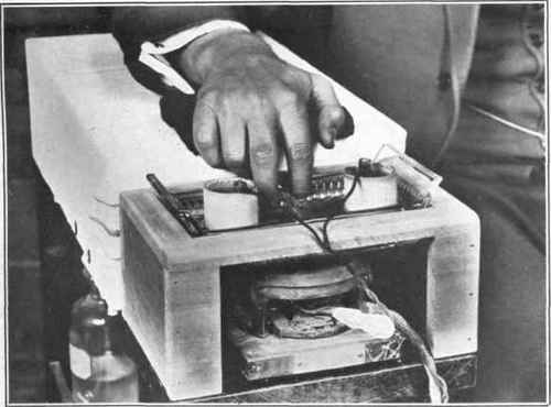
Fig. 48. - The non-polarizable electrodes for the finger tips with means of controlling the temperature.
The natural and comfortable position of the subject's hand is evident.
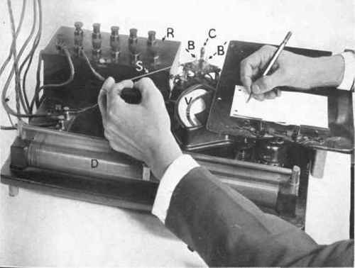
Fig. 49. - Apparatus for controlling the voltage of the shocks and for intermittently short-circuiting them.
D, drop wire across 220 volts; V, voltmeter of standard make; R, 200,000 ohms resistance; C, control switch; B and B', vacuum bulbs (parts of control switch), each containing 1 c.c. of mercury, which are noiselessly tipped back and forth to make and break the circuit. S, conveniently placed cord for operating C in breaking the circuit; a spring not visible in the illustration exerts tension on C in the opposite direction from S. The hands of the operator are shown in position for taking electrical threshold measurements.
Continue to:
My Books

