


Of the Resistance of Long Pillars
Description
This section is from the book "Elementary Principles Carpentry", by Thomas Tredgold. Also available from Amazon: Elementary Principles Of Carpentry.
Of the Resistance of Long Pillars
146. In long pillars, when the load tending to crush the material is small, the resistance to bending is nearly as the fourth power of the diameter directly; and as the square of the length inversely, as shown in the case of beams loaded transversely (Art. 100).
147. If the diameter of a cylindrical or the side of a square pillar be represented by D, the breadth and least thickness of a rectangular pillar by B and T, all in inches, the length by L in feet, and the weight that would cause the greatest amount of flexure consistent with safety by w in lbs., we have:
D4xe/L2 | = | w for square pillars; | [19] |
B x T3 x e/L2 | = | w for rectangular pillars; | [20] |
D4xe/1.7 L2 | = | w for cylindrical pillars; | [21] |
where e is a constant which varies with the kind of material.
148. In treating of the stiffness of beams to resist a cross strain, it was shown that a limit was necessary beyond which they should not deflect, in order to adapt them to the purpose of the carpenter. This limit was taken at 1/40 th of an inch for each foot of the total length.
In the case of pillars, or beams compressed in the direction of their length, and which are liable to accidental cross strains, often suddenly applied, this amount of deflection would be unsafe. Hence it is usual to limit the strain on pillars or beams under compression to that which would cause the smallest appreciable amount of deflection, or as it has been termed by the older writers on the Strength of Materials, "the point of first flexure." The determination of this point from experiment has been attended with much uncertainty. Hodgkinson states, with reference to the theory of
Euler, " that he has sought on many occasions, hut without success, to determine experimentally some fixed point of the kind, hut so far as he could see, flexure usually commences with very small weights, such as could he of little use to load pillars with in practice.*
There appears, however, to he a point beyond which a very rapid increase in the deflection takes place with a comparatively small increase in the load. It varies from 1/3 to 1/2 of the breaking weight in the experiments of Lamande, Girard, and Hodgkinson; hut in the absence of sufficient data, by assuming the " first degree of flexure " to take place on the application of 1/10 th of the breaking weight, a limit will be obtained beyond which it would not be safe to load pillars in practice.
149. In permanent structures it may be desirable to reduce this limit still further, owing to the tendency which timber has to warp when in long and slender pieces, so that the working load on a pillar as long as 60 diameters, without lateral support, should not be more than 1/20 th part of its calculated breaking. weight.
150. To find the value of the constant e, we have from formula [19]
L2xw/D4 = e. [22]
Applying this to the experiments of Lamande on pillars of French oak 36 diameters in length (Table XVI.), and taking the load to cause " first flexure " at 1/10 th of the mean breaking weight given in the Table, we have:
Length in feet. | Side of Square in inches. | to in lbs. | Value of e. |
6.375 | 2.176 | 777.5 | 154.7 |
' Phil. Trans.,' 1840.
And from Hodgkinson's experiments on Dantzic oak of 30, 34, and 45 diameters in length (Table XVIII.), both ends being cut square:
Length in feet. | Side of Square in inches. | w in lbs. | Value of e. |
3.8417 | 1.5 | 788.8 | 2230 |
5.0417 | 1.75 | 962.5 | 2609 |
3.8417 | 1.02 | 175.4 | 2392 |
Mean | 2410 |
And for pillars of red deal 29 diameters in length (Table XIX.), the ends cut square:
4.833 | 2.0 | 1199.3 | 1751
] 51. For other kinds of timber, in the absence of experiment, we have no means of obtaining the value of e, unless we assume with Dr. Young* that it varies according to the modulus of elasticity, as in the following Table: -
Table XXIII. - Constant Numbers For Long Pillars
Kind of Wood. | Modulus of Elasticity in lbs. | Valups of e. |
Ash.......... | 1,525,500 | 1840 |
Beech................................. | 1,316,000 | 1587 |
Chestnut........................... | 1,147,500 | 1384 |
Elm.......... | 1,343,000 | 1620 |
Fir, Riga.............................. | 1,687,500 | 2035 |
" Memel.......................... | 1,957,750 | 2361 |
Larch................................... | 1,363,500 | 1645 |
Mahogany, Spanish............. | 1,255,500 | 1514 |
„ Honduras........... | 1,593,000 | 1921 |
Oak, English........................ | 1,714,500 | 2068 |
" Dantzic....................... | 1,998,000 | 2410 |
Pine, Pitch......................... | 1,252,200 | 1510 |
" Red........ | 1,840,000 | 2219 |
" Yellow...................... | 1,600,000 | 1930 |
Teak, Indian...................... | 2,167,074 | 2614 |
" African.................... | 1,728,000 | 2084 |
* ' Nat. Philos.,' vol. ii.
152. It was noticed by Hodgkinson that the strength of long pillars was greatly influenced by the form and mode of fixing of the ends; when they were flat, the strength was about three times as great as when they were rounded; and when one end was flat and the other rounded, the strength was always an arithmetical mean between the strength of pillars of the same dimensions with both ends rounded and both ends flat. The fixing firmly of a pillar with flat ends somewhat increases the strength. Of these results the following explanation is given:
" Suppose a long uniform bar were bent by a pressure at its ends, so as to take the form AbcdefB, Fig. 44, then all the curves A 6 c, cde, ef B, separated by the straight line A c e B, would be equal, since the bar is supposed to be uniform.
" The curve having taken this form, suppose the points 6 and f to be rendered immovable by some firm fixings at those points. This done, it is evident that we may remove the parts near to A and B, without at all altering the curve bedef of the part of the pillar between b and f, and consider only that part. The part bf, which alone we shall have to consider, will be equally bent at all the points b, d, f. The parts c and e, too, are points of contrary flexure; consequently the pillar is not bent in them. These points are unconstrained, except by the pressure which forces them together; and the pillar might be reduced to any degree in them, provided they were not crushed or detruded by the compressing force.
Fig. 44.
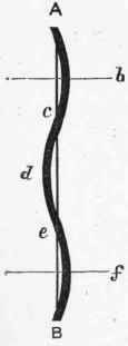
"These points may then be considered as acting like the rounded ends in the pillars experimented upon; and the part c d e of the pillar, with its ends c and e supposed to be rounded, will be bearing the same weight as the whole pillar bcdef, of double the length, with its ends 6f firmly fixed."*
153. The conclusions to be drawn from these remarks are "that long uniform pillars, with both ends rounded, break in the middle only. Those with both ends flat break in three places - at the middle and near the ends. Those with one end rounded and one flat, break at about one-third of the distance from the rounded end." †
154. Increasing the thickness of pillars in the middle adds slightly to the strength.
155. Struts or compression beams, which have their own weight to support transversely, should have their depth somewhat in excess of the thickness.
Continue to:


My Books

