An Electrically Controlled Gas Regulator
Description
This section is from the book "Handy Man's Workshop And Laboratory", by A. Russell Bond. Also available from Amazon: Handy Man's Workshop And Laboratory.
An Electrically Controlled Gas Regulator
In some work which is being carried on at various fixed temperatures, accurate and reliable gas regulation is required. The following regulator has proved entirely satisfactory:
In Fig. 163 A is a U-tube of glass, of about 8 millimeters internal diameter. This is provided with a side tube B, and is enlarged at the top for the reception of a small rubber stopper C. Through this stopper passes a tube D, the external diameter of which is 1 millimeter less than the internal diameter of the U-tube. The U-tube is filled with mercury to the level E a millimeter or so below the end of the tube D. The weight F is a piece of iron about 7 millimeters in diameter and 15 to 20 millimeters long. This is suspended freely from a hook, G, on the armature of an electro-magnet, H. The armature is held up by a spring which is fastened rigidly to a support. The spring is adjusted to support the weight but to yield quickly to the magnet. The length of the hook G must be such that its end will have a vertical motion of I or 2 millimeters. More motion than this is not required, but will do no harm. The suspension of the weight must be flexible and free rather than rigid, so that the weight acts simply by its own weight on the mercury. If the sudden motion of the armature be rigidly and suddenly transmitted to the mercury, the mercury may be caused to splash into the side tube V.
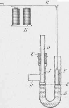
Fig. 163 - Electrically-controlled gas regulator.
The gas enters through tube D and, normally, flows under the lower end of this tube up through the annular space about it and out to the burner through the side tube B. When the electromagnet is actuated the lowering of the weight F causes a corresponding elevation of the mercury in the other leg of the tube, which cuts off the gas. A pinhole at J keeps the burner lit. In constructing the apparatus, two or three very small pinholes may be made and closed with paraffin. One or more of these may be opened with a hot needle as the size of the burner or stove may require for a pilot flame, or the burner may be supplied with an independent supply of gas to keep it lit. The surface tension of mercury is so great that though the weight F fits only loosely in the tube, the mercury will not enter the annular space around it. Thus the weight acts as well as an airtight piston. On the other side the pressure of the gas is not sufficient to drive the mercury into the annular space there. To take full advantage of this, the gas should enter through the central tube D and go out at B, and not the reverse. A motion of only about 1 millimeter is required for the weight F, and as this weighs only about 7 grammes, the work required of the electro-magnet is very slight.
For the electro-magnet an ordinary electric bell of the cheapest form may be used, the vibratory make-and-break being short-circuited and the bell removed. The weight may then be hung on the end of the clapper. The magnet should be wound up to 20 ohms to economize current.
The apparatus may be controlled by any of the forms of electrical regulators on the market, in which a contact is made when a certain temperature is exceeded and broken when the tempera-ture- goes down. As these regulators may be made of extreme sensitiveness, the regulation of temperature to any required accuracy may be accomplished.
The advantage of this form of regulator is thai it can be made quickly and easily out of materials at hand in the chemical laboratory. It may be readily cleaned. The large gas opening permits of much fouling of the mercury before cleaning is required.
In Fig. 164 is shown another way of using the same principle. In this a block of cast iron, about 2 x 2 x 3/4 inches or 60 x 60 x 18 millimeters, is taken and the tubes made by drilling holes in it. As the most of these correspond to the tubes in the other figure and are lettered the same way, they will not be redescribed. The main holes may be the same size as the tubes in the other figure, or may be of any size suitable for the supply of gas required. A plug, K, may be used to regulate the height of the mercury in the U-tube. Should the mercury become foul, it may be removed by taking out this plug, cleaned, and replaced. The inlet tube is made in the shape shown, its lower part being turned down, so as to leave the proper space for the gas. Its upper portion is threaded with a straight thread, so as to screw into the block. When it is put in place, the lock nut L is screwed on firmly over the lead washer M. Then the hole X is drilled through the block and into the tube D. The outer end of this hole is closed by a screw plug provided with a lead washer. A hole is drilled so as to intersect the hole N. This is continued by the small hole 0, which opens into the outlet B. A pointed screw P serves as a needle valve to regulate the by-pass and supply any amount of gas desired to keep the burner or stove lit.
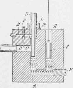
Fig. 164 - Another form of gas regulator.
A gas-pipe thread may be cut on the extreme upper end of D, and the supply pipe screwed on directly. The hole B is tapped to receive the iron gas pipe for the burner. The advantage of this form over the other is that being entirely of metal it is unbreakable and compact and eliminates any fear of fire. The operation is the same as that of the other form.
Continue to:
My Books

