The Lathe
Description
This section is from the book "Handy Man's Workshop And Laboratory", by A. Russell Bond. Also available from Amazon: Handy Man's Workshop And Laboratory.
The Lathe
A substantial lathe such as shown in Fig. 30 may be built as follows:
The legs. A, are made from 2 x 4-inch timber, 3 feet 3 inches in length. They are spread 5 inches at the top, and 1 foot 6 inches at the bottom: the 4 x 6-inch pieces, B, being cut to fit between each pair.
The lathe-bed, C, is 5 feet 6 inches long, made of 3-inch by 7 1/2-inch lumber. A 2-inch-wide slot is cut out of the center, running the length of the pieces, to within 2 inches of each end, as shown in the general view of the lathe, and in larger detail in Fig. 31. A more accurate job will be the result, if a slot is cut in a solid piece of timber, instead of using two lengths, joined together at each end, with distance pieces.
The right-hand pair of legs shown in general view. Fig. 30, is 6 inches from the end of lathe-bed, while the other pair is 9 inches, on account of the head-stock which overhangs them. The half joints for these legs are marked 1 in Fig. 31, a section being given, bearing the same number.
The joints, marked 2, are for the head-stock, D. There is need for only one of these, on the belt side of the lathe, but two are shown in case the lathe should be turned into a foot-power machine. A section is given marked 2, to correspond with the plan, in which it will be seen that the slope of the cuts is about 1/2 or 3/4 of an inch from the edges of the 2-inch groove, or slot, at the top, and the same distance from the outside edge at the bottom.
Fig. 32 shows the details of the head-stock, D, and Fig. 33 the tail-stock, E. The tongue of the latter must have a sliding fit, so that when the wedges are taken out, the stock can be adjusted to suit the various lengths of material to be turned. The tongue of the head-stock, D, can be a tight fit, and when once set up accurately, need not again be moved.
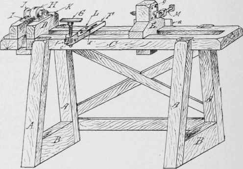
Fig. 30 - The lathe without the treadle mechanism.
The height of the head-stock is 10 inches, including the tongue, which is 6 inches. The running length is 6 1/2 inches, the width being the same as the bed of the lathe, namely, 7 1/2 inches. The V-shaped opening for the belt is 2 1/2 inches wide, being a continuation of the section marked 2, in Fig. 31. The mortices for the wedges are spaced 1 1/2 inches from the ends and should be cut 2 3/4 inches from the hearing face of the head-stock, so that when the wedges are driven home the stock will he drawn up tight. The wedges are made from hard wood, rounded along the edges and ends. They are about 6 inches long, and should have a taper of about 1/2 inch, likewise the mortises.
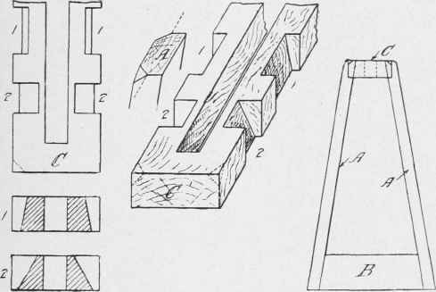
Fig. 31 - Construction of frame.
The tail-stock, E, is 7 1/2 inches wide, to suit the width of the lathe-bed. The guide, a, is 1 inch thick by 7 1/2 inches long. It is secured to the stock with screws, allowance being made for enabling the stock to slide, as stated above. It is 4 inches wide, there being but one wedge. The full height, including the tongue, which is the same as that of the head-stock, is 13 inches. The location of the plates, g, referred to elsewhere, will depend upon the size of the bearings, I, shown in detail in Fig. 34.
The tool rest and clamp F, G, and L, Fig. 35, can be made of either hard wood, or metal. The length of the clamp F is 9 inches, width 2 inches, and thickness 1 inch, the body for the rest being 2 1/4 inches deep. A small plate c is tapped for a thumbscrew f, about 7/16 inch diameter. L is an ordinary squareheaded bolt of suitable length, 5/8 inch diameter, furnished with a cruciform claw, 4 inches square, outside dimensions. A metal nut, d, 1 1/4 inches square, shaped to fit the groove in the clamp F, is threaded to take the bolt, L. The rest, G, can be made of either metal or wood. The pulley, H, has a 2-inch face, and is 3 1/2 inches diameter. It is made of hard wood, and is secured to the spindle, K, described in the previous article. A plate, J, is secured to the outside edge of the head-stock, to take the thrust coming upon the spindle, or chuck, K, when work is being turned in the lathe. At M is shown a 5/8-inch adjusting screw, with the end brought to a cone-shaped point. The plates, g, are tapped to suit, and are secured to the stock, flush with the outside face, with wood screws. The corners throughout the job are chamfered, and the surfaces made smooth.
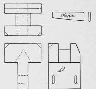
Fig. 32 - Details of head-stock.

Fig. 33 - The tail-stock.
The pulley H is belted to a driving pulley on a countershaft. Should it be desired to make a foot-power lathe, a couple of bearings can be secured to the blocks B, and a crank shaft run through. The flywheel should be heavy, and a light guard should be placed around, as it will have to be on the outside to come under the head-stock pulley, H.
Almost any kind of wood will do for the general construction, but yellow pine will be found serviceable, and give weight to the lathe, otherwise it may be found necessary to anchor it down to the shop floor, if driven by power from the saw.
In Fig. 36 are given the changes necessary for a foot-power lathe. A blacksmith will make the crank shaft for a small sum.
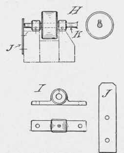
Fig. 34 - The spindle.
The wheel can be procured from almost any junk dealer. The treadle is made from two 1-inch by 4-inch strips, hinged to the back stay, and a distance piece. An ordinary staple, clinched on the underside, will do for holding the eye end of the connecting-rod, a hook being formed at the other end to slip over the crank.
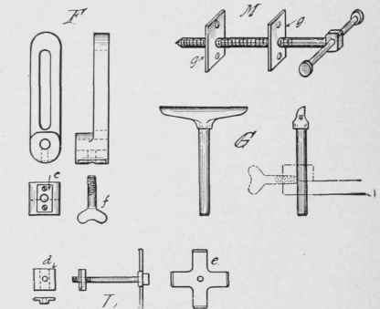
Fig. 35 - The tool rest and tail screw.

Fig. 36 - The treadle mechanism.
Extension For Speed Lathe Beds
When it is desired to turn a piece of work which is longer than the bed of your lathe the scheme illustrated in the accompanying photograph will he found useful. Take two strips of wood equal in width to the depth of the lathe bed, letting them extend out as far as desired. Screw a block the width of the lathe bed across the ends of the side strips, so as to hold the end firm, and in alinement. Also screw two strips inside of the side strips at the closed end, of a length equal to the poppet head. leaving a slot of the same width as the slot in top of lathe bed and flush with side strips, which will hold the poppet head in alinement with chuck.

Fig. 37 - Extension for speed lathes.
Screw a piece of bar iron across the side strips at the front. Bore a hole in the center of the bar for a bolt which should run through same and also through a similar iron strip beneath lathe bed parallel with upper strip. This will clamp the front end of side strips firmly to the bed. Also fasten another strip near the end of the lathe bed and resting on bed to support the extension and keep it in alinement with upper face of bed. A series of holes may be drilled through the side strips so that a bolt may pass through same close to rear end of lathe bed which will clamp the side strips rigidly to the sides of the lathe bed. The construction makes it possible to draw out the extension to any desired degree. The writer has found this to be a very useful attachment.
Continue to:
My Books

