Chucks For Long Objects Supported At Both Ends. Part 4
Description
This section is from the book "Turning And Mechanical Manipulation", by Charles Holtzapffel. Also available from Amazon: Turning and Mechanical Manipulation.
Chucks For Long Objects Supported At Both Ends. Part 4
Want of equilibrium, due to the unequal distribution of weight, in the work and the heart shaped and other carriers, may be inconveniently felt in the effect called "backlash." Directly the tool is removed from the work, the carrier falls away from contact with the driver, and rambles backwards and forwards, crossing the centers of the lathe during revolution; and, on replacing the tool, the driving contact is taken up with a jerk, which is injurious to the work and also liable to damage the cutting edge of the tool. The backlash is considerably diminished by attaching the driver to the carrier ; this may be done by binding them together with wire, or by some mechanical arrangement, of which the forked driver fig. 208, is an example; but even when so attached, the contact between the carrier and the driver will still always vary, when the tool is off and with it is on the work.
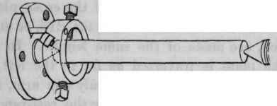
The Ring carrier with four screws fig. 212, serves for cylindrical works of a large range in diameter, the circular form ensures its equilibrium, and the driving pin, which is fixed to the carrier and loosely fits a narrow slit in the chuck, reduces the oscillations of the backlash to a minimum. The driver chucks are frequently provided with an interchangeable hollow center, fig. 205, for occasional use for works pointed at both extremities; but, if the hollow center be often required, it is preferable to have distinct chucks, to avoid the deterioration in the truth of the centers, caused by frequent removal.
The revolution of the pointed center- supporting the work, introduces a liability to error, arising from wear and other circumstances, which may prevent the center from being precisely concentric with the axis of the lathe; the same amount of error is then transferred to the work, and a cylinder turned in such case is not perfectly true or concentric with its axis of rotation. The dead center lathe, in which, while the work revolves the center remains at rest, is necessarily free from this error of eccentricity, and it is still therefore frequently resorted to, for works requiring considerable accuracy.
Fig. 212.
The difficulty experienced in turning a cylinder of the highest attainable accuracy, also arises from many other causes, besides that of want of positive truth in revolving centers; elasticity, interferes in various ways, and in addition, the resistance the work offers to the tool, and the strain caused by the contact of the carrier with the driver, tend to twist the work between them and to place its surface slightly out of truth. Mr. Clement contrived a driving chuck, in which two points of contact exert equal and opposite force upon the carrier, which materially diminishes any error arising from torsion.
Fig. 213. Fig. 214. Fig. 215. Fig. 216.

The Double-self acting driver chuck of Mr. Clement, is shown dotted with the carrier in outline in fig. 213; with the carrier dotted in fig. 214, and also by fig. 215, a diagram to explain the action of the chuck. The chuck as before, consists of a round plate or flange with a steel pointed center, having in addition a strong plate in the form of a cross, sliding diametrically upon its face, where it is retained by two fixed studs, shaded in fig. 215. Two driving pins are used, inserted in any two of the several pairs of holes, tapped at the same distance on either side of the diametrical line of the cross plate ; and the two ends of the heart or bar carrier fig. 216, or any other that may be used, are made of the same length. In the diagram fig. 215, the plate is traversed as far to the left as the studs will allow, and if the carrier had only one arm, as usual, the revolution of the lathe, would convey the resistance to the tool through the carrier to the upper pin; this, being fixed in a yielding slide, would travel to the right until checked by the studs, when it would drive the work round by a single pin, without correction as before. As however the carrier used with the chuck has two equal arms, when the one end meets the upper pin, the cross slide can only move until the other end of the carrier, shown dotted fig. 215, meets the lower pin, when the two pins serve as equal points of resistance to each other, conveying equal and opposite forces to each end of the carrier. To prevent backlash, a third pin is placed in the cross piece and loosely retains one end of the heart carrier as in a fork; the hooked extremities of the bar carrier fig. 216, embrace the pins, and serve the same purpose.
Fig. 217.
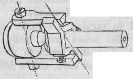
Fig. 218.
The double driver chuck fig. 217, has been made after several different forms, but all having the common feature of the two driving pins connected together, moving as one piece on pivots placed diametrically across the chuck. The driver and pivots, which in this particular form of the chuck admit of only one radial distance, are shown separately by fig. 218. Less efficient than Clement's double driver chuck, they are also comparatively weaker, in the same degree that fig. 204, is to fig. 206; the general forms of which, these chucks may be considered to follow.
The work hitherto referred to as mounted between centers, has been concentric; but portions are frequently required to be turned eccentric to the general axis, and either parallel with, or at various angles to it, when two or more pairs of centers become necessary.
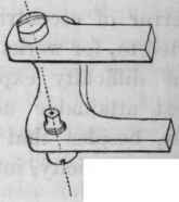
When the eccentricity is parallel to the axis and is also sufficiently small, as in the crank fig. 219, the two pairs of centers are made in the object itself; the centers 1 - 1, serve for the principal and concentric portion of the solid, and the centers 2 - 2, for turning the eccentric or crank. It is however essential, that the four centres should be in one plant and their relative distances equal, otherwise the two axial lines of the crank will be oblique instead of parallel; the effeet of any such obliquity being doubled, by the crank rod or hook oscillating twice as much as the angle of error, causing wear and straining of the parts of the mechanism. To correctly set out these centers, fig. 219, should be laid at rest in a fixed horizontal position upon a true plane surface, such as fig. 8G8, Vol. II., while a line is marked at each end, passing through the centers 1 - 2, the same height from and parallel with the surface; after which, it only remains to mark the centers upon these lines with the linear distance exactly alike between each pair. Work of irregular or curved form is supported on the surface plate by blocks of wood or metal, placed beneath any projecting or raised portions and so arranged, as neither to interfere in scribing the lines nor to raise the work from taking its fair bearing on the surface plate.
Continue to:
My Books

