Anchor. Continued
Description
This section is from "The American Cyclopaedia", by George Ripley And Charles A. Dana. Also available from Amazon: The New American Cyclopædia. 16 volumes complete..
Anchor. Continued
A sufficient number of wrought-iron bars made from the best scrap iron, or from "Welsh mine iron," are bound together by iron hoops, forming the faggot; this is placed in a specially contrived furnace, where it is brought to a white or welding heat, when it is removed by the aid of a crane to the anvil, and subjected to the rapid and powerful blows of the stamping hammer. When an approximate form is thus obtained, the finishing is done by heavy sledges in the hands of the anchor smiths. The arms and stock may be forged separately and then welded together at the crown, or, as in the process patented by Mr. Perrins of England, the whole may be built up by the welding together in a given order of a number of separate pieces, so adjusted as to secure the greatest strength in the direction of the heaviest strain. When the stock is of wood, it consists of two beams, generally oak, mortised in the centre so that they may embrace the square, upon which they are firmly bolted; the middle thickness should be one twelfth of the length, and the whole should taper from the centre out, the diameter of the end being about one halt that at the centre.
The iron stock, which is rapidly replacing that of wood, is a simple round bar tipped with knobs, which prevent its entering the ground, and with one end bent at right angles. This passes through a hole in the square which is rounded out for the purpose, and is held in position by a metal ring or shoulder upon one side, and a slit and key on the other; by removing this key, the whole stock may be driven through, and thus, owing to the crook upon the end, be doubled down upon the shank, rendering it much more compact and portable. - So important is the quality of strength in an anchor, that all modifications of the tried and approved form, or any improvements that have the appearance of sacrificing strength to convenience in handling, or even gain in holding power, seem to have been regarded with suspicion. Hence the anchornowin general use might almost have been described a century ago. In 1833 Lieut. Rodger of the English navy received letters patent for an improvement in the size and form of the palms, "having found by experience that anchors with small palms will not only hold better than with large ones, but that the arms of the anchor, even without palms, have been found to take more secure hold of the ground than anchors of the old construction of similar weight and length." He fixed upon one fifth of the length of the arm as a suitable proportion for the length or the depth of the palm.
The palm of the anchor, instead of being flat, presents two inclined planes, calculated for cutting the sand or mud instead of resisting perpendicularly. The Lenox, Mitcheson, and Aylen anchors are all improvements on the old admiralty pattern; while the Isaac anchor, an American invention, has a flat bar of iron passing from palm to palm, in addition to which two other bars unite the ends of the stock to the centre of the shank, intended to prevent the fouling of the cable. A novel and in many respects important improvement is that of the Porter anchor, having movable flukes or arms; this anchor, with certain valuable alterations, is represented above as the "Trotman anchor." It will be readily seen that, by the closing of the upper arm against the shank, the chances of fouling are greatly decreased, as also the danger of the ship's grounding upon her anchor in shallow water. The accompanying table, showing the relative order in which the several anchors above mentioned stand with regard to each of the properties essential to a good anchor, was embodied in a report made by a committee of five ship owners appointed by the lords of the admiralty to test their relative merits.
The names are arranged alphabetically:
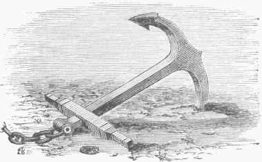
Fig. 1. - Common Anchor.

Fig. 2. - Admiralty Anchor.

Fig. 8. - Trotman Anchor.
ANCHOR. | Strength computed from first crack. | Holding long and short scope. | Facility of storing. | Quick holding. | Quick tripping. | Exemption from fouling. | Facility of sweeping. | Facility of transport in boats. | Fishing in a heavy sea way. | Canting. |
Admiralty . | 4 | 5 | 1 | 2 | 1 | 4 | 1 | 2 | 2 | 2 |
Avion..... | 7 | 4 | 1 | 2 | 3 | 4 | 1 | 2 | 2 | 5 |
Porter, or | 2 | 2 | 3 | 4 | 2 | 1 | 4 | 3 | 5 | 3 |
Honiball | ||||||||||
1 | 6 | 4 | 5 | 1 | l | 4 | 4 | 5 | 1 | |
Lenox..... | 6 | 3 | 2 | 1 | 2 | 3 | 2 | 1 | 3 | 2 |
Mitcheson . | Trial refused. | 1 | 3 | 1 | 3 | 2 | 3 | 2 | 4 | 4 |
5 | 2 | 1 | 1 | 2 | 4 | 2 | 1 | 1 | 2 | |
Trotman.... | 3 | 1 | 3 | 3 | 4 | 1 | 4 | 3 | 5 | 5 |
The estimated numerical values of these several anchors are as follows: Trotman, 1 .28; Rodger, 1.26; Mitcheson, 1.20; Lenox, 1.13; Porter, 1.09; Aylen, 1.09; Admiralty, 1, standard; Isaac, 0.73. Notwithstanding the above favorable report, the Trotman anchor has not been received with general favor by ship masters, though largely used by the merchant steamers. - In general service, anchors rank according to their size and weight, as follows: bower, sheet or stream, and kedge; and a competent authority recommends them in the following order: the Lenox and Rodger for bower, Mitcheson for sheet, and Trotman for a shore anchor. - The anchor adopted by the United States navy is solid with an iron stock, and as a rule its weight is proportionally less than the English standard, our officers preferring a smaller anchor with greater length of chain. The following table gives the relative-size of chains to anchors of given weight, and is compiled from the navy regulations on this subject:
Weght of anchor. | Size of chain. | |||
8,000 | lbs | 2 1/16 | inches. | |
6.000 | " | 1 13/16 | " | |
4,000 | " | 1 9/16 | " | |
2.000 | " | 1 2/16 | " | |
1,000 | " | 13/16 | ' | |
The following is a reduced table of "Lloyd's Regulations tor the Number and Weights of Anchors for Merchant Vessels ":
Ship's Tonnage. | Bower. | Stream. | Kedge. | Bower, Wood Stock. | Bower, Iron Stock. | Stream. | Kedge. | Second i Kedge.' |
Tons. | Cwt. | Cwt. | Cwt. | Cwt. | Cwt. | |||
50 | 2 | 1 | 1 | 3 | 4 | 1 1/2 | ||
100 | 2 | 1 | 1 | 5 | 7 | 2 1/2 | 1 1/4 | |
250 | 3 | 1 | 1 | 13 | 15 | 5 | 2k | |
500 | 3 | 1 | 2 | 23 | 26 | 9 | 4 1/2 | |
1.000 | 3 | 1 | 2 | 35 | 41 | 12 | 6 3/4 | 3 1/4 |
1.600 | 3 | 1 | 2 | 43 | 50 | 14 | 8 1/4 | 4 |
2,000 | 4 | 1 | 2 | 47 | 54 | 14 | 9 | 4 1/2 |
In addition to these various forms of common anchors, there are numerous devices designed for special service. Among these are the grapnel and mushroom anchors shown in fig. 4. The former is adapted for securing light craft,- and the latter - a solid concavo metal plate with central shank - is only used where permanent anchorage is desired, as for light-ships, buoys, etc. The latest novelty is an anchor with an elastic shank. The principle of having a spring between the soil and the vessel is evidently excellent, as it is certain that without the natural spring formed by the curve in the chain it could never withstand the sudden jerks from a mass of several hundred tons, though the better place for the spring seems to be on board rather than in immediate contact with the rough sea bottom.
Continue to:
My Books

