


Regulating Apparatus
Description
This section is from the book "Welding Theory, Practice, Apparatus And Tests Electric, Thermit And Hot-Flame Processes", by Richard N. Hart. Also available from Amazon: Welding: Theory, Practice, Apparatus And Tests, Electric, Thermit And Hot-Flame Processes.
Regulating Apparatus
Regulating apparatus includes a switch-board on which are assembled a reactive coil, rheostat, potential indicator, and fuse blocks and switches; and apparatus for automatically shutting off the current of the primary when welding heat is reached.
The reactive coil (Fig. 17) is to control the current at the welder when a great variety of sizes is to be welded. It consists of an iron base, a copper hood, a switch, and two laminated iron cores; the smaller core carries the copper hood and partly rotates within the larger core which has four distinct coils wound on it. These coils can be connected either in series, series multiple, or multiple, by means of the switch in the base, which is operated by the handle projecting through side of base. The hood is moved over the winding by a worm gear, which is operated by the wheel at the front.
When the switch handle is in position No. 1 and the hood farthest away from the winding, the minimum current is obtained. When the switch handle is in position No. 2 and the hood farthest away from the winding, the mean current is obtained.
When the switch handle is in position No. 3 and the hood over the winding, the maximum current is obtained.
The reactive coil also regulates the potential for metals like iron, which are good conductors when cold and become more resistant when hot.
A fairly efficient makeshift rheostat was formerly made of a barrel of water into which a metal disk was lowered and raised. The disk served as one pole and the bottom of the barrel as the other pole. The sides of the barrel were insulated. Regarding the high peak loads caused by a large Thomson machine, The Electrical Times1 has this to say: "Central station engineers have hitherto been somewhat chary in connecting electric welders of large size to their mains on account of the fluctuating nature of the load, although there are numerous instances of small welders being so used. A very interesting installation has recently been completed in London by the Electric Welding Company, Limited, in which a welder of 90 k.w. capacity is worked off a single-phase power supply at 400 volts. In order to prevent undue fluctuations of voltage on the mains, a special substitutional resistance is installed, built in three sections, each controlled by a switch, so that one or more sections can be put in circuit according to the size of the work being welded. A large liquid resistance is also employed to prevent an undue rush of current, when the primary circuit of the welding transformer is closed, the plates being raised and lowered by a small motor through suitable gearing. The controlling switch of the welder is so arranged that when put in the 'on' position it starts the plate-lowering gear, thus gradually cutting out the starting resistance, and vice versa. This plant is in continuous operation, and no inconvenience to other power users in the neighborhood has been reported. Another welder of smaller size has also been connected to this circuit. In this case a special economy coil is used as a regulating device.

Fig. 17. - Thomson type reactive coil, for controlling current in welding machine.
September 5, 1907.
"To facilitate the working of electric welding machines on polyphase circuits, Professor Elihu Thomson has recently patented a method of winding the transformers to prevent unbalancing the phases. This will doubtless lead to considerable development in the near future, seeing that the power companies' supply mains are available in most manufacturing centres." panies' supply mains are available in most manufacturing centres."
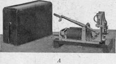

Fig. 18. - Two types of Thomson automatic break switches.
On account of the type of welds it handles, the Thomson welder is often made automatic. Suppose a welder is being fed links of a chain to be welded. If the welder .will put through each weld automatically, a uniform product will be secured and labor, time, and current will be saved. The automatic shut-off (Fig. 18, a) is a switch in the primary circuit which is thrown open as soon as the clamps move together on the yielding metal. The current is not used any longer than is necessary to heat the joint.
The break-switch shown in figure 18, a is used with the larger welders, heavy currents being employed, and should be installed at the back of the welder. The switch is out of reach and is operated with the foot by the lever; this lever should run under the base of the welder, the end projecting at the front of the welder at a convenient place for the operator.
The break-switch shown in figure 18, b is used with the smaller welders for wire and thin flat sections, etc., when the weld is made instantaneously and should be installed at a convenient height against the left of the welder. The switch is operated by hand, the lever being pressed down on to the shoulder at the front, where it locks, being automatically released when the weld is made, by a cut-out device on the welder, a spring throwing up the lever.

Fig. 19. - Thomson universal welder with horizontal oblique clamping device and hydraulic jack for pipe straight-away and miscellaneous work.
When the piece to be welded does not heat evenly, the lever should be lightly and intermittently pressed against the shoulder without locking, until the heat is evenly distributed, when it should be locked, as before stated.
Continue to:


My Books

