Instructions For Operating. Continued
Description
This section is from the book "Workshop Receipts For Manufacturers And Scientific Amateurs. Supplement Aluminium To Wireless", by The Chemical Publishing Co.. Also available from Amazon: Workshop Receipts For Manufacturers And Scientific Amateurs.
Instructions For Operating. Continued
The Gate
This is swung from a horizontal spindle projecting from the mechanism case, to which it is attached by a bayonet joint. This method of attachment ensures a most rigid support, with the advantage that the whole gate can instantly be detached for inspection and cleaning. The pressure runners are mounted in a separate frame in the gate, and the pressure can be instantly adjusted by two knurled knobs. The runners themselves and the film plate are made of highly-polished stainless steel. The fixed runners on the front side of the gate can be removed and new ones quickly fitted if this should be necessary. The runners on the back of the gate are removed for cleaning purposes simply by a half-turn of a screw.
The Cradle
The " keep " rollers for the intermittent sprocket are fitted in a cradle separate from the gate. This cradle carries two rollers, and is pivoted to the lower part of the gate to allow of adjustment to suit the position of the intermittent sprocket.
Threading up is facilitated by the free wheel top sprocket, which, by allowing the film to be drawn out of the top spool box, saves the operator the time and inconvenience of cranking sufficient film to provide an efficient " thread up."
Automatic Shutter
A very sensitive cut-off shutter is fitted behind the film trap, operated by the simplest and most reliable method known, viz., oil attraction between two flat surfaces. Directly the film reaches a safe speed the shutter opens, but closes the instant the machine is stopped.
Maltese Cross Action
The cross is extra large and cut solid with its spindle, and accurately ground to size. An adjustment is provided that is both simple and reliable, by means of an eccentric bush 4 inches long, fitted with phosphor-bronze bearings. The whole movement, cross, bearings, etc., is kept flooded with oil from the oil bath in the projector casing.
Lamp House is of extra large size with two full-size doors taking the largest arc lamp manufactured. It is well ventilated, is made of sheet steel riveted to iron frame supports and lined throughout with asbestos. An extra heavy asbestos back curtain fitted on a sliding holder is provided.
Condenser And Slide Stage
The condenser lenses are fitted into a spring mounting carried in a cast frame and provided with a large handle to facilitate removal. Slide carrier with double-curtain cut-off is also provided.
Spool Boxes
Strongly constructed of Russian iron asbestos lined, extra large and wide, thus the film is more quickly threaded. A separate cast-iron arm carries the lower spool box, and is attached by means of set screws to a machined face on the side of the mechanism table. The top box spindle is fitted with a steel plate and a spring-loaded plunger, which gives an even pressure on the spool, and ensures smooth and silent running.
The Stand
This has received very careful attention, and has been designed to accommodate the various parts of the machine with a correct distribution of weight between the legs. The solid cast-iron top is well ribbed and shaped to receive the lower spool box, so as to shorten the distance from the gate and reduce the amount of exposed film to a minimum. This top also provides a platform for a driving motor directly above the front legs. The wrought-iron telescopic legs are fitted with small hand wheels for tilting the top, which can be clamped in position.
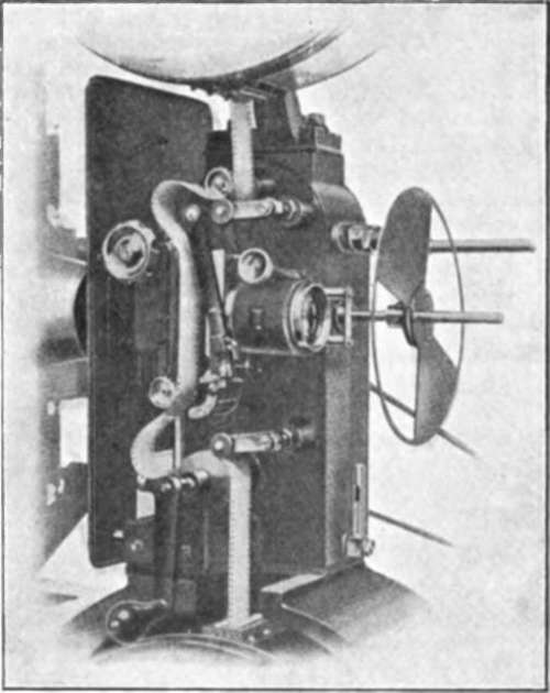
Fig. 41.
Motor Drive
The motor is in a very accessible position, away from the film, and drives direct by leather belt to the fly-wheel. The sliding speed regulator is screwed to the stand beneath the lamp house.
Rewind
The take up spool is driven direct from the vertical shaft of the mechanism through spiral gears. These gears and the adjustable friction mechanism are totally enclosed in an extension of the cast support for the spool box. Large-diameter double-fibre friction washers are fitted, and the spring pressure can be adjusted by a knurled brass knob at the rear of the casing.
Fig. 41 gives a view of the film gate and gear arrangements, and also shows the safety traps at the film entry and exit into the spool boxes.
Continue to:
My Books

