Microscopes
Description
This section is from the book "Workshop Receipts For Manufacturers And Scientific Amateurs. Supplement Aluminium To Wireless", by The Chemical Publishing Co.. Also available from Amazon: Workshop Receipts For Manufacturers And Scientific Amateurs.
Microscopes
The following matter on the proper use and care of the microscopes made by them has been supplied bv Messrs. W. Watson & Sons, Ltd., London, and it is believed that such information will be found very useful.
Fig. 120 illustrates a microscope with a plain stage, and Fig. 121 that with a mechanical stage. The numbers in each Figure refer to parts described as follows :-
1 ;Milled heads attached to pinion of coarse adjustment.
2 ;Rackwork which engages the pinion for coarse adjustment.
3 ;Screws for adjusting tension between rack and pinion coarse adjustment.
4 ;Milled head controlling fine adjustment.
5 ;Screws for taking up wear in fine adjustment fitting.
6 ;Fulcrum of lever of fine adjustment.
7 ;Stage springs.
8 ;Holes for fitting stage forceps, side silver reflector, etc.
9 ;Underfitting.
10 ;Eyepiece or ocular.
11 ;Drawtube.
12 ;Female thread to which objectives are attached.
13 ;Axis joint.
14 ;Tail-piece.
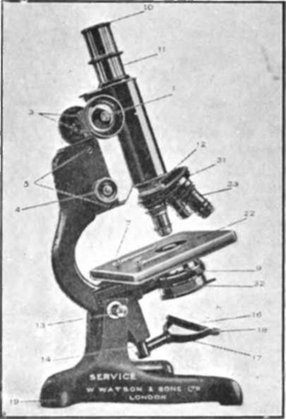
Fig. 120.
15 ;Sliding mirror fitting.
16 ;Mirror.
17 ;Mirror arm.
18 ;Mirror gimbal.
19 ;Foot.
20 ;Reader for fine adjustment.
21 ;Divisions to fine adjustment milled head.
22 ;The Stage
Fig. 120 plain.
Fig. 121, mechanical.
23 ;Milled head controlling vertical movement of mechanical stage.
24 ;Milled head controlling horizontal movement of mechanical stage.
25 ;Compound substage.
20 Screws for centreing the compound substage to the optical axis of the microscope.

Fig. 121.
27 ;Milled head controlling rackwork for raising and lowering substage.
28 ;Spring slots of fine adjustment.
29 ;Plate covering spring box of fine adjustment.
30 ;Screws for taking up wear in coarse adjustment fitting.
31 Revolving triple nosepiece, carrying 3 objectives.
32 ;Abbe Illuminator.
33 ;Objectives.
To Set Up For Use
The first thing to decide is whether an artificial illuminant shall be employed or daylight.
Daylight
The majority of workers find it inconvenient to work by daylight, and it is objectionable for more than one reason. In the first place, the light is not of a constant quality, and in the next-in order to obtain the finest effects with the microscope, it is necessary that the light in the room should be, as far as possible, confined to that which illuminates the microscope only, so that the worker himself is practically in the dark.
If daylight is used, a window facing north is* generally to be preferred, and the best illumination is obtained from white clouds. Direct sunlight must be avoided.
Artificial Illumination
Oil-
For visual work, no light is superior to the lamps regularly sold for microscopic work, having usually a Jin. flat wick. When such a lamp is employed, the flat of the flame is used under all conditions other than when a substage condenser is employed.
Electric Light
The increasing use of electric light and the many advantages that it gives for clear and brilliant illumination has led to the introduction of special lamps for microscopical work. The most useful form is the frosted or opal bulb in an enclosing hood with an aperture for the light. It is admirable for the greater portion of the work that is done, when the resolving power of the objective is not to be tried to its utmost capacity necessitating " Critical " illumination.
We will now proceed to set up the microscope with a low-power objective.
It will be well first of all that an acquaintance be made with the direction of movement produced by turning the milled heads. The milled heads of both coarse and fine adjustments (Figs. 120and 121), when turned clockwise, bring the tube nearer the stage 22.
The object is placed on the surface of the stage 22 in the illustration, beneath the spring clips, 7.
One of the objectives is removed from its brass box and screwed into the lower end of the microscope body at the part marked 12.
One of the eyepieces is inserted at the upper end of the body, at 10.
The body should be racked downwards by means of the milled heads, 1, until the front of the objective almost touches the object, and as far as possible the object that is to be viewed should be set immediately under the objective.
The mirror 16 should then be so set as to receive light from the illuminant and direct it to the object on the stage. For this purpose it may be necessary to slide the fitting 15 on the tail-piece 14, and the gimbal ring 18 should be turned on the arm 17.
Very gently rack the body upwards by means of the milled heads 1 until the object comes into view. Then to get the sharpest possible definition, the fine adjustment milled head 4 may be turned.
It may be that in racking the body tube upwards the object does not come into view in consequence of its not being exactly beneath the objective. In such a case, it will be best to rack the body down again to the point from which it started and then very gradually raise it, watching to see if any specks come into the field. The appearance of anything of this kind will indicate that some slight defect on the object slip has been focussed, and it will then only be necessary to move the object on the stage surface until it comes into the field of the optical system. A very small amount of practice will render the user proficient in doing this.
Extra Low-Power Objectives
In order to use objectives of 3 inches and 4 inches focus, for which, in microscopes of compact build there is sometimes not sufficient rack-work adjustment, we include a fitting carrying the standard size of screw for objectives at the lower end of the draw-tube. These objectives should be attached to the screw, which is accessible by unscrewing the collar in which the drawtube slides.
High-Power Objectives
With high-power objectives, assuming that no substage condenser is used, the same procedure would take place as with the low-power objectives, excepting only that the front of the objective would have to be made to actually touch the object before racking upwards, and a greater amount of accuracy is necessary in setting the object in the field, on account of the increased magnification. As the working distance of high-power objectives-from 1 /6in. upwards- is very short indeed, the front lens almost touching the object, it is necessary that subjects under observation be covered with thin cover glass.
Continue to:
My Books

