The Scleroscope
Description
This section is from the book "Workshop Receipts For Manufacturers And Scientific Amateurs. Supplement Aluminium To Wireless", by The Chemical Publishing Co.. Also available from Amazon: Workshop Receipts For Manufacturers And Scientific Amateurs.
The Scleroscope
The principle employed in this portable hardness tester is the measurement of the height of rebound of a diamond-pointed hammer which falls a fixed distance upon the surface being tested. This rebound is read off against a graduated scale.
The scale against which the hammer rebounds are measured consists of units which are determined by dividing the average rebound from quenched pure high carbon steels into 100 equal parts. These rebounds run from 95 to 105 degrees. The scale is continued higher than 100 to include metals having exceptionally high or super-hardness, not unlike thermometer scales which are carried higher than the boiling point of water, and which in the Centigrade scale has been taken as the round number of 100, with freezing point of water as zero.
Fig. 86 shows the mechanism for raising and dropping the hammer, the action is as follows :-In the automatic instruments manufactured since 1910 the necessary valves, suction for hammer and its release, are all alternately operated by one bulb and tube (A), acting on the cam (B), through medium of piston (C), the adjustable oscillator (D), and the end rachets (E). When the hammer is down, after having made a drop or test through medium of bulb (A), it will be found impossible to suck it up by the vacuum formed on releasing hold on said bulb, because the valve (F) is then wide open and held so by cam (13). By again pressing bulb (A), however, it turns the cam to the neutral quarter so that valve (F) is allowed to seat itself, thus closing it and placing the glass tube chamber in direct suction communication with the hand bulb. When now this bulb is suddenly released it will cause a vacuum and thus suck up the plunger hammer (G) so that it is caught by the right and left hooks (H).
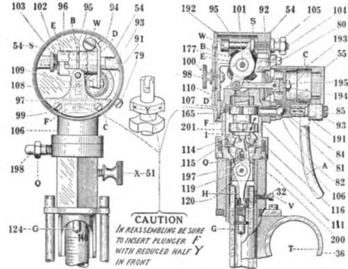
Fig. 86.
When now the hand bulb is pressed again, the cam (B) acts on the valve (F) unseating it so that there will be free access of air to the glass tube when the hammer falls. The hammer is released a moment after opening the valve by means of the hollow steel cone (I) acting on the oscillating hooks (H).
Set Instrument Plumb
In any case that a test is made the instrument should be as nearly level as possible as indicated by the bob rod on the right side of the tube barrel. When the instrument is on its clamping stand it is levelled by the tripod screws, when on the swing arm the latter will be mounted level by aid of the plumb bob, while when used free handed the same means is always relied upon.
Making A Test-The Surface
The piece to be tested, especially when the hardness is high, should always present a level surface, if it is only a small spot where the diamond-tipped hammer is to fall on, and also the harder the material the smoother must the surface be, although it must not actually be polished. Decarbonized surfaces must positively be removed before testing. Since it is the height of the rebound of the hammer which is to be noted, and the top of same is the indicator, this is the part that has to be watched in its relation to, or position on the scale, the moment it comes to rest again to drop after the first rebound.
First, when hardened steel is tested, look near 100, for medium hard around 50 and for soft metals, around 10 or 15 and so on, then you have the range.
Second, in making the first hit it is well to watch from a little extra distance to help in getting the range better on each unknown specimen. Thus, if it seems to be a rebound up to between say 70 and 90, etc., you know about what the next rebound will be and which may then be read exactly. Now, the watch word is, never look above the range already found, but rather a few points below, for then if the rebound is higher you will easily see it; if it is less it will not come within the range of focussed vision and will be missed.
Illumination
Always have the light fall downward on the instrument so that the glistening on the top of the hammer will act as a guide, and whether it is artificial or day light, let it be strong enough. Much depends on this.
The scleroscope is provided with a lens and a pointer needle which together may be adjusted to any part of the scale and is used as follows :-Suppose we want to test a piece of metal and wish to read very positively, slight differences, the rebound is to a given figure as the first trial test shows. By now setting the lens and needle at this figure, it is seen that slight variations above or below are easily noted. The lens is used principally on soft metals. Owing to the comparatively limited rebound of the universal hammer when used on very soft metals, there has developed a demand for a hammer with a larger point area. This enables it to rebound higher, thus magnifying small but significant variations in hardness. These hammers go with the regular testing set, but they are not intended for use in ordering material to specification.
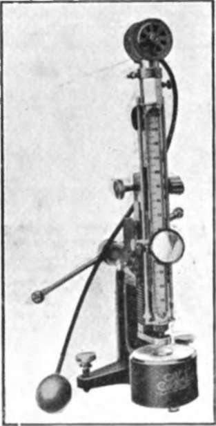
Fig. 87.
Changing Of Hammers
Draw the hammer up to its hook (H), then loosen the screw on the hexagon of the tube barrel and simply lift off the automatic head and the hammer will be carried along on the hook. The hammer should always be carefully cleaned before inserting to avoid the possibility of rusting or sticking.
Inserting Glass Tubes
(1) Locate the small set-screw (V) in back of the instrument which serves to hold the glass tube by pressing against a saddle of brass which is a section of the barrel cut-out and again replaced so that it may conform to the glass tube properly. Loosening this screw, therefore, will release the glass so that it may be withdrawn, for said glasses are not cemented in.
(2) After inserting the new glass, refasten the little set-screw referred to, as it was before, but caution must be exercised to use only very gentle pressure to avoid such strains as may break the glass.
If the glass does not form air-light connection with the barrel, a sliver of thin paper cemented on the paper ring will answer the requirement, but the glass tube itself must not be cemented in the barrel.
Fig. 87 illustrates the general appearance of this hardness tester.
Continue to:
My Books

