Torque Converters. The Constantinesco Torque Converter
Description
This section is from the book "Workshop Receipts For Manufacturers And Scientific Amateurs. Supplement Aluminium To Wireless", by The Chemical Publishing Co.. Also available from Amazon: Workshop Receipts For Manufacturers And Scientific Amateurs.
Torque Converters. The Constantinesco Torque Converter
The effect of this Torque Converter applied to, say a motor-car, is to give an infinitely variable gear without the use of the usual gearbox, or clutch, the car speed being controlled by the throttle only. The principle of the working of this invention is not easy to explain clearly and briefly. Figs. 204 to 207 show from different phases of a simple experiment dealing with a rod or stick having one end loaded with a weight, on the right hand side of each fig. is shown the representation of the same arrangement (as on the left hand in each case) but translated into mechanical shape, etc. In Fig. 204 everything is stationary, the top hand supporting the weight of the rod and weight, on the right hand side of the same fig. the upper hand is replaced by a swinging link, and the lower hand by a connecting rod attached to a crank. In Fig. 205 the whole is shown as in slow motion, the weighted stick swinging slowly to and fro, but imparting no motion to the two small rods shown near the top right hand. In Figs. 20G and 207 the arrangement is in modorale and rapid motion respectively, and it will be seen that in the case of moderate motion the upper hand on the link is moved backwards and forwards to some extent. In the case of rapid motion this backward and forward motion becomes more pronounced. Now considering the three cases of slow, moderate and rapid motion, it will be seen that the apparent fulcrum of motion of the weighted rod, etc., alters from a position at the top end to one at the lower end, and moreover it does this by gradual stages depending upon the speed of vibration given to the whole by the lower hand on the drive. Fig. 208 shows a diagram which illustrates the principle of a model made to demonstrate the Torque Converter, the model being devised by Messrs. Meccano Ltd.
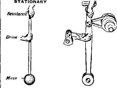
Fig. 204.

Fig. 205.

Fig. 206.

Fig. 207.
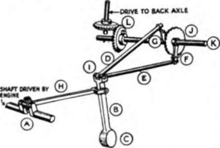
Fig. 208.
The crank (A) driven by the engine, is connected to a lever (B), to the lower end of which is fixed a heavy weight (C) forming a pendulum. The other end of the lever (B) is connected to two rods (D and E) carrying pawls (F and G) which bear on a ratchet wheel (J). In this manner the torque, or twisting effect, is delivered to the rod (K) and through it by bevel gears and shaft (L) to the differential on the back axle (not shown in the diagram). No matter whether the rods (D and E) be pushed towards the ratchet or pulled away from it, the turning motion imparted by the pawls to the rod (K) is always constant in direction.
This model is not a replica of the actual Torque Converter, but is to simply demonstrate the working principles. It shows how the rotating of the crank A causes the lever on rod B to oscillate and thereby cause rods D and E to operate pawls F and G, and so turn wheel J. If there is no load on the back axle then the engine, etc., turning the crank A can turn rapidly, and thereby impart rapid movement of the pawls F and G, and so turn the axle rapidly. If the load on the back axle be heavy then the engine finding more work, slows down, and imparts a smaller movement to pawls F and G, see Fig. 208. In the actual Torque Converter the pawls are replaced by what the inventer terms " valves" and these are the subject of a patent not yet disclosed, but it is understood that the valves are without any back-lash, i.e., no lost motion such as takes place in the action of pawls on raehets, and are uni-directional in motion.
It may be of real interest to those specially interested in the Torque Converter to construct a working model, and therefore the following details and figs, supplied by Messrs. Meccano Ltd. are given. The cost of all necessary parts is a matter of shillings only, and an unusually instructive model is the result.
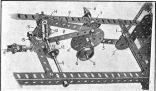
Fig. 209.
Building The Model
The Meccano model of the Torque Converter may be constructed as follows. The rod 1 (Fig. 209) is rotated by a sprocket chain from the electric motor fitted to the chassis. This rod carries a triple throw eccentric (2) which is connected by a 3in. strip (3) to the centre of a face plate (4). A short rod (5) passes through the lower hole of the face plate and carries two flanged wheels (6) which act as the pendulum weight. The rod (5) and the weights (6) are suspended by two cranks (7) from the short pivotal rod (8) mounted on the main member of the frame as shown. Two 41/2in. strips (9) are connected to the top hole of the face plate (4) and their other ends are connected to elements each formed by two couplings (10) secured on short rods, the couplings rocking loosely on the driven rod (11) from which the drive to the differential is conveyed through the bevels (12). Two pawls (13) are mounted on short rods secured in the outer holes of the coupling (shown more clearly in Fig. 210), which is a view from below, these pawls being controlled by short tension springs (14) so that they are kept in contact with a lin. gear wheel (15). When moving in one direction they trail idly over this gear wheel, but when moving in the other direction, they drive the gear wheel (15) and consequently the rod (11) to which the wheel is secured.
Continue to:
My Books

