


Drawing. Part 3
Description
This section is from the book "Manual Instruction: Woodwork. The English Sloyd", by S. Barter. Also available from Amazon: Manual Instruction: Woodwork.
Drawing. Part 3
It will then be seen that the folding planes are not really requisite, and fig. 6 is only introduced to make the problem and its solution clear. The distance of a given point in front of the vertical plane can then always be measured below the xy, fig. 7, or assumed trace of the co-ordinate planes, and the height above or the distance below the horizontal plane, projected by a continuous straight line passing through the x y at right angles.
Several other instances are given in figs. 6, 7. It must be remembered that the folding of the vertical plane is downward in the portion above the xy, and upward in the portion below it.
As a consequence both plan and elevation are above the xy when a given point is behind the vertical plane and above the horizontal plane; and conversely, if the point is below the horizontal plane, and in front of the vertical plane, both plan and elevation will be below the xy. When the point is below the horizontal plane and behind the vertical plane, the plan is above the xy and the elevation below it.
Fig. 8 is a sketch showing the principle of projection in the case of a block of wood, which is some distance in front of the vertical plane, above the horizontal plane, and parallel to both.

Fig. 7.
There is nothing fresh in this. The plan to be adopted is quite the same as with the points - in fact, it merely involves the projection of a succession of points, to be afterwards joined.
From the foregoing it will be observed that lines are seen their real length in the plane to which they are parallel, and lines at right angles to these planes of projection are necessarily shown as points in them.

Fig. 8.
Now, to obtain an end elevation a new vertical plane must be set up on x2 y2, at right angles to both co-ordinate planes, and parallel to the end of the block. Draw the new x2y2 at any convenient distance and project the end of the block in the usual way.
The elevation of the end may be turned down into the horizontal plane, opposite the end of the plan, or the new plane may be swung round to the old vertical plane, and then turned down to the horizontal plane like any other elevation.
Fig. 9 shows the drawing of plan elevation and end elevation, as it is to be actually drawn, fig. 8 being only given to show the imaginary planes and the projectors falling on them.
It may be desired to obtain the elevation of this block of wood from a point of view other than that shown in fig. 8 - i.e., with its vertical faces inclined to the vertical plane, the long faces making, say, 30° to the vertical plane, and the short ones, of course, at 60°.
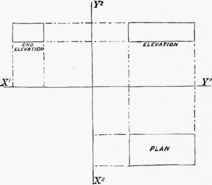
Fig. 9.
Fig. 10 shows the plan and elevation of a block of wood in a similar position as that in fig. 9, with a new x2 y2 at 30° to the long faces.
The vertical trace of this plane is omitted as unnecessary. This x2y2 is the horizontal trace of a new vertical plane on which will be seen the new aspect of the slab.
This problem involves what is called change of ground line.
A series of projectors should be drawn at right angles to x2 y2, and the heights of the slab marked off as in elevation, for the height of the block is the same on the new plane as on the old vertical plane.
The instance just given shows the projection of lines inclined to a vertical plane, but parallel to the horizontal plane, and shows the shortening of the lines in projection caused by their inclination to the plane of projection; but if a line is inclined to both planes, it will not be shown its real length in either plan or elevation. Fig. 11 shows a line a b inclined to both horizontal plane and vertical plane, with its projection in those planes.

Fig. 10.
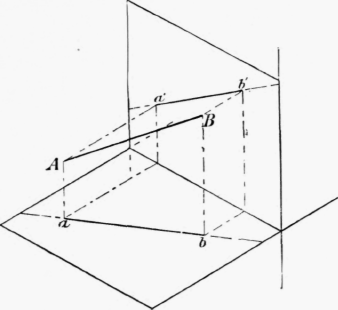
Fig. 11.
Fig. 12 shows the actual drawing of this line in plan and elevation. To find its real length set up a new plane on the plan a b, and indicate its trace by a new x2 y2.
Now a b lies wholly in the new vertical plane, and if this is folded down, the real length of the line will be seen on the horizontal plane. Eight projectors from a and b will therefore pass through the ends of the line a b, and their distance from the x2y2 can be obtained by reference to the heights in the elevation. The length of the line can be obtained in the same way from the elevation by drawing a new x3 y3 on a' b'. This is the vertical trace of a new plane at right angles to the vertical plane, and containing a. b.
Draw right projectors showing the distance a b are in front of the vertical plane, which are, of course, shown in the plan. This will be equivalent to folding the new plane into the vertical plane, and would give the real length of the line.
Continue to:


My Books

