Drawing. Part 4
Description
This section is from the book "Manual Instruction: Woodwork. The English Sloyd", by S. Barter. Also available from Amazon: Manual Instruction: Woodwork.
Drawing. Part 4
A model may be made of cardboard or paper similar to fig. 11, and will serve to bring this problem very clearly before the reader.
Sections. - To obtain the section of any figure is really a form of change of ground line. A plane is imagined through the object at any desired position, and in cutting through makes the section.
Fig. 13 shows the elevation of a slab of wood having a raised panel. Draw the traces of a plane cutting through this object, as in the illustration. This plan may be either turned down into the horizontal plane or wheeled into the vertical plane.

Fig. 12.
Project the plan from the elevation. At any convenient distance from the elevation on the vertical plane, draw a vertical line to give the back of the slab.
The shaded figure shows the development of the section on a b, the thicknesses at the various points being taken with the dividers from the plan.

Fig. 13.
It will be noticed that this plane of section was not turned down into the vertical plane in its original place, as we should then have had the elevation and section confused in one drawing while the projection of the plane of section into a clear part of the paper saves possible difficulties from this cause.
The horizontal section of this slab on cd, as shown in fig. 14, is even simpler than the vertical section.
The new plane, of course, would give the new plan on top of the old one, and again, to prevent confusion, it is drawn a little lower down.
Isometric Projection
This form of projection is invaluable for rectilinear drawing, and, because of its pictorial nature, a child can see at a glance what he would perhaps have much difficulty in recognising by orthographic projection alone, and as an assistance in understanding plan, elevation, and section, it is very valuable.
Deftness in the use of the set-squares and neatness in execution are also obtained by this attractive and agreeable form of drawing. Working drawings of isometric projection cannot be used in making any other than rectilinear figures, but when it is remembered that these are by far the most numerous of mechanical drawings, the scope of this form of projection will be seen to be still great.
The theory of isometric projection can be best understood by drawing the projection of a cube standing on one corner, with one diagonal vertical to the plane of projection. Now all the edges of the cube are of equal length and are equally inclined to the plane of projection. They are, therefore, projected of equal lengths in that plane, though the projection will not, of course, give the real length of the edges.

Fig. 14.
Draw three lines of equal length, meeting in a point, and making 120° with each other. These make the projection of the front solid angle of the cube, and these lines are called the isometric axes, as from these all measurements are to be made.
Complete the cube, as shown in fig. 15, by drawing the opposite parallel edges to the isometric axes, using the set-square.
Notice that the diagonals of the faces are shown in some cases foreshortened, as a f, a g, and a e, and in the other cases, being parallel to the plane of projection, as b c, c d, and d b, they are shown their real length. Thus, none of the diagonals of the faces being inclined to the plane of projection at the same angle as the edges, measurements which will apply to the latter, or to lines parallel to them, will not serve for any other dimension.
Hence the unsuitability of this form of drawing for any other than rectangular figures.
The real length of the edge is reduced in the projection in the following ratio: As 2√3 : 2√2 Therefore, to put the case inversely, the isometric is to the real length as the 2√2 to 2√3. The proof of this will be seen by a reference to fig. 16 and to Euclid i. 47 and vi. 4.

Fig. 15.
Fig. 16 shows the section of the cube on acea', and contains two sides, a c and a' e, and two diagonals of faces a e and A' c.
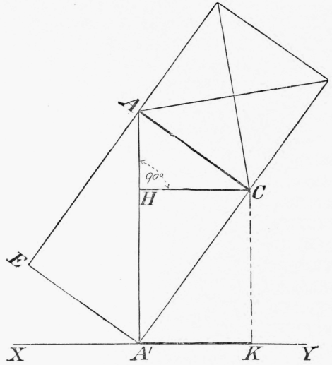
Fig. 16.
Now the proportion of the edge of a cube to the diagonal of its face is as 2√1 : 2√2 (Euclid i. 47), and as AC=2√1 and AE = 2√2, the diagonal of the cube a a', being the side which subtends the right angle formed by them, = 2√3.
Draw CH, and project it into x y at a' k.
Now the triangles aea' and aca' are equal, and ach and a a' c being similar triangles, their sides are in common ratio.
Therefore a c is to c h :: 2√3 : 2√2; but ch=a'k, which is the projected length of a c, and therefore the real length of the side is to the projected length as 2√3 to 2√2. Based on these facts, Professor Farish devised a system of measurement to be applied to any rectilinear figure standing with its isometric axes equally inclined to the plane of projection, with the object of making this form of drawing serve the purpose of both plan, elevation, and section. Knowing the proportion of the real to the isometric length of any line, it is an easy matter to make an isometric scale.
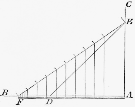
Fig. 17.
Draw two lines a b and a c perpendicular to each other, and mark off on them equal parts at d and e, as in fig. 17 : join d e.
Now de = 2√2 and a e 2√1.
Mark off on ab, a f, equal in length to d e.
Now, as ae = 2√1 and af=2√2, therefore ef, which should now be drawn, = 2√3.
Real length measurements on e f, therefore, can be shown isometrically on af by dropping lines parallel to e a from any given point in ef to af. Any of these lines will complete a triangle in common ratio to aef.
And as a f is the isometric length of e f, so any distance in e f can be shown on a f similarly.
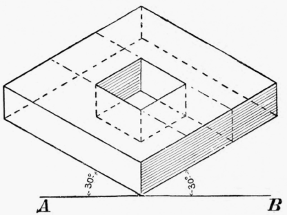
Fig. 18.
Draw on ef any plane scale, and in this way make an isometric scale of it.
The somewhat difficult reasoning of this problem is not intended for children, but the teacher must thoroughly grasp it.
Boys should be taught to use any plane scale isometrically, and, although this is not strictly correct, it has the great advantage of giving a pictorial representation, in which all measurement in, or parallel to, the isometric axes can be shown in the same scale. Fig. 18 is an instance of a plane scale used isometrically. A slab of wood 5/8 in. thick and 3 ins. square, with a square hole in the middle, is drawn to scale 1/2.
On the ground line a b set up a perpendicular 5/8 in. high. From the top of this draw two lines 3 ins. long at 30° to a b. These three lines give the isometric axes, and based on them the figure may be rapidly drawn with the pencil and 30° set-square.
Sometimes forms not actually rectilinear can be drawn isometrically.
Fig. 19 shows the face of a pentagonal slab, and fig. 20 the same drawn isometrically.
The rectangle is drawn round this figure in order to accomplish the object, for after putting the rectangle in isometric projection, it is a simple matter to mark the points of the pentagon on the new projection, and draw the figure in.

Fig. 19.
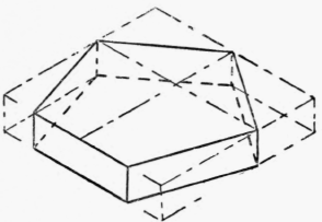
Fig. 20.
Round a series of points obtained in this way, the circle in fig. 21 may be sketched in isometric projection, as shown in fig. 22.
There is another way of making the isometric projection of this circle. In isometric drawing, one diagonal of a square will be shown its real length, and this may be at once drawn, ab.
Lines at 30° from each end of ab will give the inclination of the edges, and their intersection will define their isometric length.
Join these points of intersection and the short diagonal is obtained.
The point where the circle cuts the diagonal may be obtained from fig. 21 and marked on ab. Now lines parallel to the edges through these points and the centre will give all the points in fig. 21, and the circle may be drawn in.
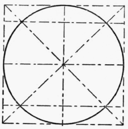
Fig. 21.
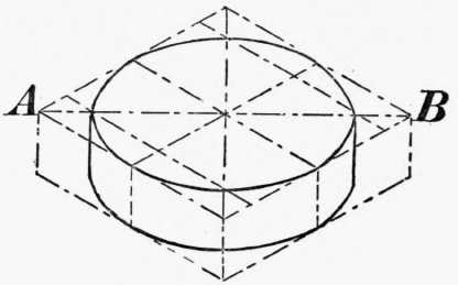
Fig. 22.
In both the pentagon and the circle only one dimension, it will be noticed, is seen its real length, indicated by the scale, proving by illustration the practical uselessness of isometric projection for working drawings of any but rectilinear figures.
Continue to:
My Books

