


Model XIII. - A Hanging Newspaper Rack
Description
This section is from the book "Manual Instruction: Woodwork. The English Sloyd", by S. Barter. Also available from Amazon: Manual Instruction: Woodwork.
Model XIII. - A Hanging Newspaper Rack
Fig. 202. As An Alternative To The Preceding
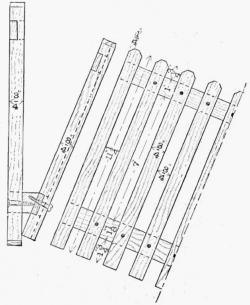
The drawing of the front elevation shows on one side the back, and on the other the appearance of the completed rack. The side elevation should be made, and if the rails have been drawn in the elevation, they need not be made as shown in the new projection on the side elevation - another case of change of ground line. The plans show the joints of the bottom rail and the sloping front. The two methods of putting on the rails, by simply nailing, or by grooving and nailing, are also indicated.
Yellow deal, bass-wood (American lime), or walnut will all make good material for the model. For the back framing, three strips, each 13 1/2 ins. by 1 1/4 in. by 1 in., will be required, from which to make the top and uprights, and one 13 1/2 ins. by 2 ins. by 1 1/4 in. for the bottom rail.
The sloping front will require two strips 13 1/2 ins. long and 3/4 in. thick, but one should be 1 1/4 in. wide while the other should be 1 3/8 in. These pieces are for the top and bottom rail, and on these the laths are to be fastened. These are made from seven strips 3/8 in. thick, 1 in. wide, and 1 ft. long.

Half elevation of back.
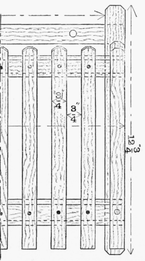
Half of complete elevation.
Side elevation. Half elevation of front.


Plan of bottom rail.

Plan of front with rails nailed on.

Plan of front with rails let in.
Fig. 202.
The two end posts of the front can be made from two strips 1 ft. long and 1 in. square.
The back framing should be planed up and made first. The top rail is halved into the stiles, as shown in the isometric projection, a, in fig. 203. These joints are screwed up from the back with 5/8-in. screws. The bottom rail is notched out at the end, to take the upright stiles, b, in fig. 203. The bottom rail and back, it will be noticed, are not secured with the half-lap joint.
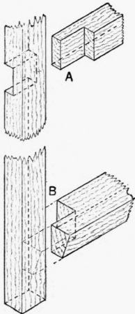
Fig. 203.
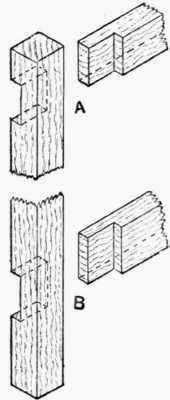
Fig. 204.
Before putting in the bottom rail, however, the front edge must be bevelled off with the plane to the required angle, marking on the ends and one side the waste to be removed, and, as the planing progresses, testing the work with the bevel set at the same angle. Screws 1 1/4 in. long should be used to fasten the rail and back together.
The sloping front is made similarly to the back, the top is halved into the end rails, making the notched halving joint as shown at a, in fig. 204.
The bottom rail is jointed in the same way as shown in fig. 204, b.
The parallel strips to make the sloping rails should be planed up true to dimensions, the top corners chamfered off, and nailed on at the proper intervals. The horns on both pieces of framing should be chamfered and made true by vertical paring, and the two holes in the top back rail should be bored. The sloping front can be screwed on, using 1 1/4-in. round-headed screws, when the model will be complete.
Continue to:


My Books

