


Model XIX. - A Standing Picture Frame
Description
This section is from the book "Manual Instruction: Woodwork. The English Sloyd", by S. Barter. Also available from Amazon: Manual Instruction: Woodwork.
Model XIX. - A Standing Picture Frame
Fig. 231
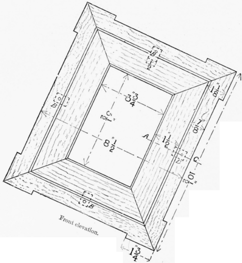
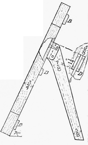
The drawing of this model should be the side elevation, giving the angle of the front and the back leg, the front elevation b, Buttons ; d, Projected back view of block to receive leg.
Side elevation.
Fig. 231.
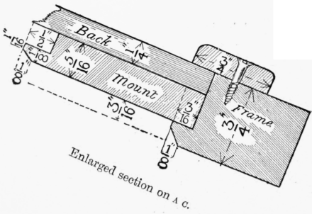
showing a case of change of ground line, and a fall-size detail of section on a c, in fig. 231.
The timber for this frame should be some ornamental wood, say walnut or mahogany, for the outside frame and the leg, and sycamore for the mount; the back may be made of bass-wood or yellow deal.
The size of this model will be regulated by the dimensions of the picture to be framed, but it is not advisable to attempt to make a very large frame, as the practical difficulty in performing a large piece of work is altogether out of proportion to the increase in the dimensions. The size of the frame recommended is shown in the illustration (fig. 231), and this will take an ordinary cabinet photograph. Presuming that this size is adopted, the timber required will be as follows: -
Walnut or Mahogany - Two strips 11 ins. long, 1 1/4 in. wide, and § in. thick, and two of 9 1/2 ins. long each, and remaining dimensions similar, for the frame; one strip 8 ins. long, 1 1/4 in. wide, and 1/4 in. thick, for the leg; one piece 3 1/2 ins. long, 5/8 in. wide by 1/4 in. thick, from which to make the four stops, and one 2 ins. long by 3/4 in. square for the supporting block of the leg, D.
Sycamore - 2 ft. 9 ins. by 2 ins. by 1/2 in. for the mount.
Yellow deal - One piece 10 ins. long, 7 1/2 ins. wide, and 3/8 in. thick for the back.
The wood should first be planed up true to dimensions except the strip for the mount, which should be left a little wide, and then the four strips for the outer framework should be taken up, and the rebate and chamfer made on the face edge of each piece, as shown in the section (fig. 231).
The mitred joint may be of any form previously attempted, but, perhaps, the stopped, grooved, and cross-tongued joint is the best in this case, as the joint will then be similar on both sides, and no unsightly tongue will show through on the edges at the corner.
The portion to be removed on the outer edges of the frame should be cut out before glueing the frame together. The notches should be sawn down to the required depth, and the waste roughly removed with a chisel, leaving just a little more work to be done to it after glueing up.
The joints can be very conveniently brought up close, by tying a piece of string tightly round the outside of the framework, with notched pieces of wood made to fit each corner of the frame, as shown at a in fig. 232, to act as cramps on the joints, and to prevent the string from damaging the corners of the frame. The blocks, it will be noticed, are made to give fibres at right angles to the strain of the string. They can be readily made from a small strip of wood rebated on one corner, and then cut into four pieces, as in fig. 233. The rebate, which will be in contact with the newly-made joint, should be oiled to prevent it from becoming attached.
The string is tightened up by inserting slips of wood (b, in fig. 232), halfway between each corner, and turning them round in the same way as the string of a bow saw. To prevent the string from slipping off the block to either side, a little notch should be made in the middle of the outer angle of each block, and in adjusting the string for tightening, take care to make the pressure occur immediately over the middle of each joint; if the string pulls obliquely, the increasing strain might cause the joints to open, and so spoil them.
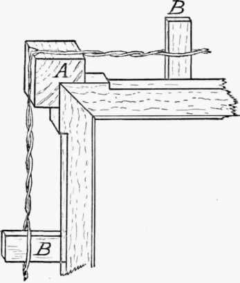
Fig. 232.
The strip of wood for the mount should now be rebated and chamfered to the dimensions shown in the section, fig. 231, and then cut into the lengths for each side, and the mitres shot as usual. This wood is so thin that the only joint possible is the grooved and cross-tongued mitre. The tongue should be a small piece of veneer, or some equally thin wood, and the groove, as shown in fig. 234, ought to be made with one cut of a panel or tenon saw - about 3/8 in. deep.
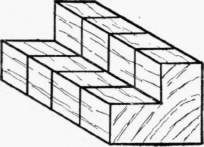
Fig. 233.

Fig. 234.
To make the four joints of the mount, they may, after glueing, be brought tight up by nailing just round the edges on the smooth surface of another piece of wood, as in fig. 235.
Some care in adjusting the four joints will be required, and it is of the greatest importance to keep the whole surface quite flat.
To prevent the back of the mount from adhering to the wood under it, by the glue which will be squeezed out in putting in the nails, a piece of paper should be laid down first. When dry, the nails should be drawn with the pincers, and the outer edges of the mount shot true to the proper dimensions. The paper should be cleaned off the back, and the face also smoothed off. The paring of the outer edge of the frame can now be completed, and the mount fitted in. The back should be fitted, and the small stops to secure it prepared. They should be fastened down with 1/2-in. screws with slightly countersunk heads. These screws should not be driven in too far, so as to allow the buttons to be readily pivoted. The leg may now be modelled with saw and file to dimensions, and the small block to take it prepared. They should be screwed together with two small screws - one from each side as shown in the elevation (fig. 231).
The block for the back is screwed on to the back of the frame, as shown in the small projection d, in fig. 231, the screws being inserted through the back.

Fig. 235. Showing mount held together, after glueing, by nails at the angles marked n.
Continue to:


My Books

