


Model XXV. - A Footstool Involving The Haunched Tenon Joint
Description
This section is from the book "Manual Instruction: Woodwork. The English Sloyd", by S. Barter. Also available from Amazon: Manual Instruction: Woodwork.
Model XXV. - A Footstool Involving The Haunched Tenon Joint
Fig. 262
The orthographic projections should be drawn. The timber required, which may be yellow deal or pine, is as follows: -
For legs, one piece ............................. „ rails, twice ...................................
„ „ twice.....
,, top, one piece ................................
1 ft. 5 1/2 in. x 11/2 in. x 1 1/2 in.
11 in. x 1 5/8 in. x 1 in.
9 in. x 1 5/8 in. x 1 in.
12 1/2 in. x 10 1/4 in. x 3/4 in.
Plane up the wood for the legs and rails to the extreme dimensions, and saw it into four equal lengths for the legs.
Before marking the legs examine the plan of the joint in fig. 262, and the isometric projection with the haunched tenons together, fig. 263. (The leg is indicated by faint lines in order to give prominence to the joint.) It will be noticed that neither the mortices nor tenons are at mid-distance from the sides. This is in order to give as much strength to the inner angle of the leg as possible, and to secure longer tenons than if they were in the middle.
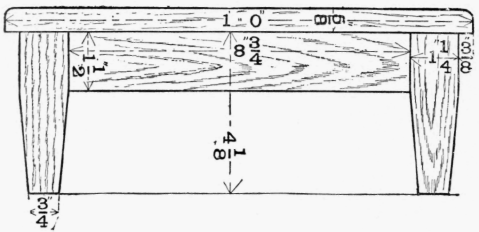
Side elevation.
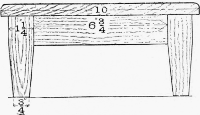
End elevation.

Plan, with portion of top removed.
Fig. 262.
Put the four legs side by side with their face sides uppermost, and gauge the limits of length and the size of the mortice, as shown in fig. 264.
Turn each leg individually, and continue the marking on the face edge. Set out the opposite rails simultaneously, and with the mortice-gauge adjusted to 1/4 in. mark the tenons on the ends of the rails and the mortices on the sides of the legs. Remove the square portion of the mortices carefully, and then pare down the haunched part of each. Fig. 265 shows the shape of the leg with the mortices made.
Now cut the tenons of the rails. They should be sawn out solid, and one corner then cut off to make the haunch, the extreme end of the tenon being roughly mitred with a chisel. Fit all the joints up, and if correct take them apart again, and cut off the waste at the bottom of the legs. Chamfer each leg with a jack and smoothing plane. To obtain lines to work from, mark the leg as in fig. 266, which shows the inner square drawn on the bottom end. Clean off the rails and glue up the joints. These may either be brought tight up in the cramp or they may be bound with a twisted string, as in the case of the picture-frame model.
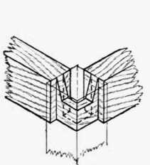
Fig. 2G3.

Fig. 264.

Fig. 265.
The top should now be planed up true and the edges rounded.
Before glueing or nailing the top on, plane off the tops of the legs.
Another method of securing the top, when the pupil wishes to hide the nails or screws, is to button it on from underneath. These buttons (about six in number) are tongued at one end and are inserted into shallow mortices. The screws, as shown in fig. 267, are then inserted.
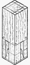
Fig. 266.
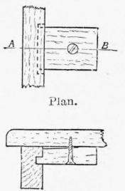
Section on a e.
Fig. 267.
Continue to:


My Books

